3
\$\begingroup\$

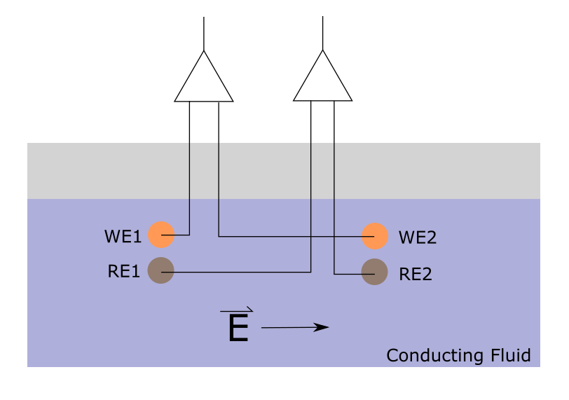
I am trying to compare two record signals coming from two INA amplifiers simultaneously. Both amplifiers are actually recording the same signal, just with different recording electrodes. We are interested in the performance comparison of the two electrode types. We are aware of input current biasing and have designed our circuitry thus far in the manner as shown below. However, the two different recording electrode types (WE vs RE) sit naturally at quite a high DC potential difference between each other. Meaning, WE electrodes in solution might be 500-1000 mV above the RE-electrodes in solution due to their Nernst potentials in our recording medium. Note: Both electrode types (Types: WE and RE, 2 each) are in the same solution at the same time.

The circuit below records... the problem is, we do not want a leakage current path connecting the WE electrodes to the RE electrodes, as this is essentially forming a battery between the two. With lower resistor values, we even saw corrosion of one recording electrode and deposition onto the other electrode type. Note: The 10M ohm resistors connecting to AGND are needed to bias the amplifiers to common mode input, but they also create a 20M ohm path between the various electrode types where roughly 100nA of current flows, killing the low leakage current feature of the INAs.

Are there any ideas on how to avoid this or go around this?

Edit for more information:

This is only a snapshot of the analog front end of the board. The power comes from an external supply and is converted to the required voltage supplies (iso+, iso-, AGND) with an isolating DC/DC converter.These power rails are common to the entire analog end.

The outputs of the INAs go to an ADC which then heads to an isolated SPI comms to communicate back to the rest of the system on Digital Ground. The electrodes are different metal types in various conducting solutions and/or acids. One could picture here ion/chemical sensing through potential measurements.

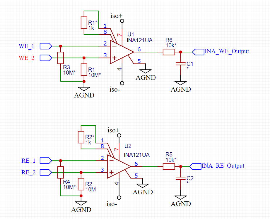
Two DC coupled Instrumentation amplifiers with bias current paths to Analog ground. An asterik indicates component not necessarily placed

Example Setup

\$\endgroup\$
13
  • \$\begingroup\$ Welcome! There's some details regarding the power supply that might be helpful and might be worth clarifying either with a clear description or in schematic form. Just to confirm, does iso+ and iso- mean that you have one supply, isolated, that both op amps are sharing? Is that supply referenced to AGND? \$\endgroup\$
    – nanofarad
    Commented Apr 10 at 19:27
  • \$\begingroup\$ The circuit below records <-- no it does not record; it's an amplifier/buffer. Maybe there's some translation thing going on? What would a battery form between the two electrodes. This is unclear. What sort of cruel environment is this located in and finally, what signal are you recording and why do you have two channels? Your schematic node names imply they are connected at the power supplies. You need to be much clearer about this and, be specific in your question because it's not clear. \$\endgroup\$
    – Andy aka
    Commented Apr 10 at 19:43
  • \$\begingroup\$ what actually are the sensors, and what environment are they in? context is everything. When describing a problem please remember that the other party does not have the contextual information that you do. \$\endgroup\$
    – danmcb
    Commented Apr 11 at 6:17
  • \$\begingroup\$ Thank you all for your comments, I edited the original post to try and address these. \$\endgroup\$ Commented Apr 11 at 7:11
  • \$\begingroup\$ 1. What would be the maximum leakage current between the two sets of electrodes that will give acceptable results? 2. Regarding the voltage signals being measured, what is the min & max expected amplitude range, & frequency range? 3. Regarding the conducting fluid, what is its temperature range? \$\endgroup\$ Commented Apr 11 at 10:06

1 Answer 1

1
\$\begingroup\$

Note: The 10M ohm resistors connecting to AGND are needed to bias the amplifiers to common mode input, but they also create a 20M ohm path between the various electrode types where roughly 100nA of current flows, killing the low leakage current feature of the INAs.

There should be no need to put these 10MΩ resistors from each electrode to the circuit GND to bias the amplifiers to common mode. The solution is to remove these resistors, and find an alternative way to achieve the same outcome.

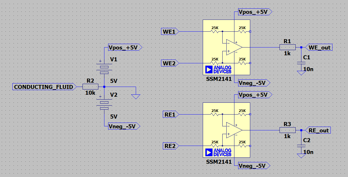
The solution should be simple: connect the conducting fluid to the AGND of your circuit, and ensure the power rails of the op-amps (INAs) have sufficient range (both positive and negative) to keep all electrode voltages within the INA121 common-mode range at all times. The datasheet of the INA121 states that the maximum supply voltage is 36V, so you could apply power supply rails of, for example, +12V & -12V, or as high as +/-18V; from what you have described, however, it would seem +/-5V should be sufficient.

The schematic below shows this idea; the connection to the conducting fluid could be via a different electrode, or perhaps to the container or pipe, provided it is sufficiently conductive.

Note that I did not have a model of the INA121, the closest I could find in the standard LTspice library is the AD SSM2141, the schematic does not show the feedback components.

enter image description here

\$\endgroup\$
5
  • 1
    \$\begingroup\$ The app note associated with the INA121 may be quite relevant. SBOA503, Importance of Input Bias Current Return Paths in Instrumentation Amplifier Applications \$\endgroup\$ Commented Apr 13 at 2:10
  • 1
    \$\begingroup\$ Thanks Fabio, I will try this next week and report back here what happens. \$\endgroup\$ Commented Apr 13 at 12:44
  • 1
    \$\begingroup\$ Excellent, looking forward to seeing your results. Note that the value of R2 is rather arbitrary here; it can probably be reduced to zero, however, leaving it as 10k may be useful as a means of measuring the current flowing into the conducting fluid from the ground connection. \$\endgroup\$ Commented Apr 14 at 9:30
  • \$\begingroup\$ Thanks Fabio for your input. I removed the resistors connecting the non-inverting inputs to AGND and simply connected AGND with a physical electrode (I did forget the R2 10k resistor but that can be done later). Doing this immediately allowed me to read values that mostly agreed with other high impedance voltmeters from the electrodes. I say mostly agreed, because depending on the electrode type used for this connection, a different DC bias (on the scale of 0.5-1 mV) was introduced in the amplifier/ADC read out. \$\endgroup\$ Commented Apr 18 at 13:49
  • 1
    \$\begingroup\$ Excellent news. If you have high-impedance volt meters to measure the electrode voltages independently, then it would be interesting to plot the reported difference voltage WE_out (& RE_out) vs the common-mode voltage at the INA121 inputs (the average of the two voltages at WE_1 & WE_2). Ideally, if WE_1 & WE_2 are connected together, & connected to a node with an adjustable voltage (lets call this voltage Vcm), then WE_out should remain at 0mV while Vcm remains within the common-mode range of the INA121 (which is stated on the datasheet). \$\endgroup\$ Commented Apr 18 at 21:52

Your Answer

By clicking “Post Your Answer”, you agree to our terms of service and acknowledge you have read our privacy policy.

Not the answer you're looking for? Browse other questions tagged or ask your own question.