Defining the requirements for an anti-aliasing low-pass filter can be a little tricky and depends heavily on your use case.
What's the problem we are trying to solve?
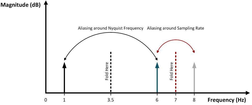
Aliasing is the effect where signals that are sampled are "folded" across the Nyquist frequency, appearing at lower frequencies. We generally treat these as noise. If we remove these signals before they are sampled this noise disappears.
 (Diagram from this TI app note)
How much noise rejection do we need?
This depends on two factors:
- How sensitive your ADC is.
- How much noise there is
How sensitive is your ADC?
The first factor is easy to figure out; for most applications, you can just look at your ADC's SNR (or, depending on your use case, SINAD, THD, SFDR, etc) in dB and target the noise to be lower than that value for it to not degrade your ADC's performance.
It looks like the STM32F415 datasheet does not have dynamic specs like SNR, so we can bound the problem with the SNR from its ENOB. ENOB (Effective Number of Bits) is a measure of the lowest noise an n-bit ADC can have based on the noise inherent in quantization. (You can learn about the pedantic detail here, disclaimer I wrote the content)
SINAD for an ADC with a n-bit ENOB is generally calculated as
$$1.78dB + 6.02dB \cdot N$$
So, a 12-bit ADC has a maximum theoretical SINAD of 74 dB (more about SINAD vs ENOB here).
How much noise do you have?
How much noise is tricky, for many applications. The first thing to consider is do you expect significant high-frequency (above Nyquist) noise while trying to acquire your normal signals.
Or, put another way, do you expect your signal, when viewed with an oscilloscope, to be swamped by high-frequency noise?
If not, you may only want to slap in a single pole filter with a cutoff at your highest frequency of interest; this is generally good enough for many applications.
If you do expect to see significant interference or a completely unknown signal (like for an oscilloscope frontend) you can limit the problem to the highest amplitude signal possible, a square wave from rail to rail on your input (generally clamped).
A square wave's fundamental frequency component is actually ~27% (2.1dB) larger than the amplitude of the square wave.
So if your input range is clamped to the input range of your ADC, then you would need SNR + 2.1dB or rejection. In this case 76dB.
How Sharp does your filter need to be?
The filter needs to have a response at Nyquist at or below the filtering value we worked out above to filter this noise out.
We can calculate the number of poles with the equation:
$$
N = \frac{\text{Rejection Required (dB)}}{20} \Big/ \log_{10}\left(\frac{\text{Nyquist}}{\text{Cutoff Freq}}\right)
$$
So the highest the filter cutoff can be for a single pole filter to get 76dB of rejection is 0.016% of the Nyquist frequency, 1.3% for 2 poles, 17% for 5 poles, etc.
How can we do better?
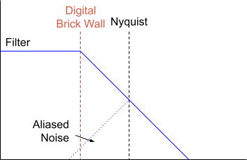
If we take advantage of the fact that digital filtering lets us achieve much higher cutoffs (effectively a brick wall), we can actually relax the filter to allow leakage all the way back to our passband, letting us trade digital complexity for analog complexity.

This means we only need:
$$
N = \frac{\text{Rejection Required (dB)}}{20} \Big/ \log_{10}\left(\frac{2 \text{ Nyquist}-\text{Cutoff Freq}}{\text{Cutoff Freq}}\right)
$$
Reducing our 76dB filter requirements to 0.03% at 1 pole, 2.5% at 2 pole, 30% at 5 pole, etc.
Applying it to your problem
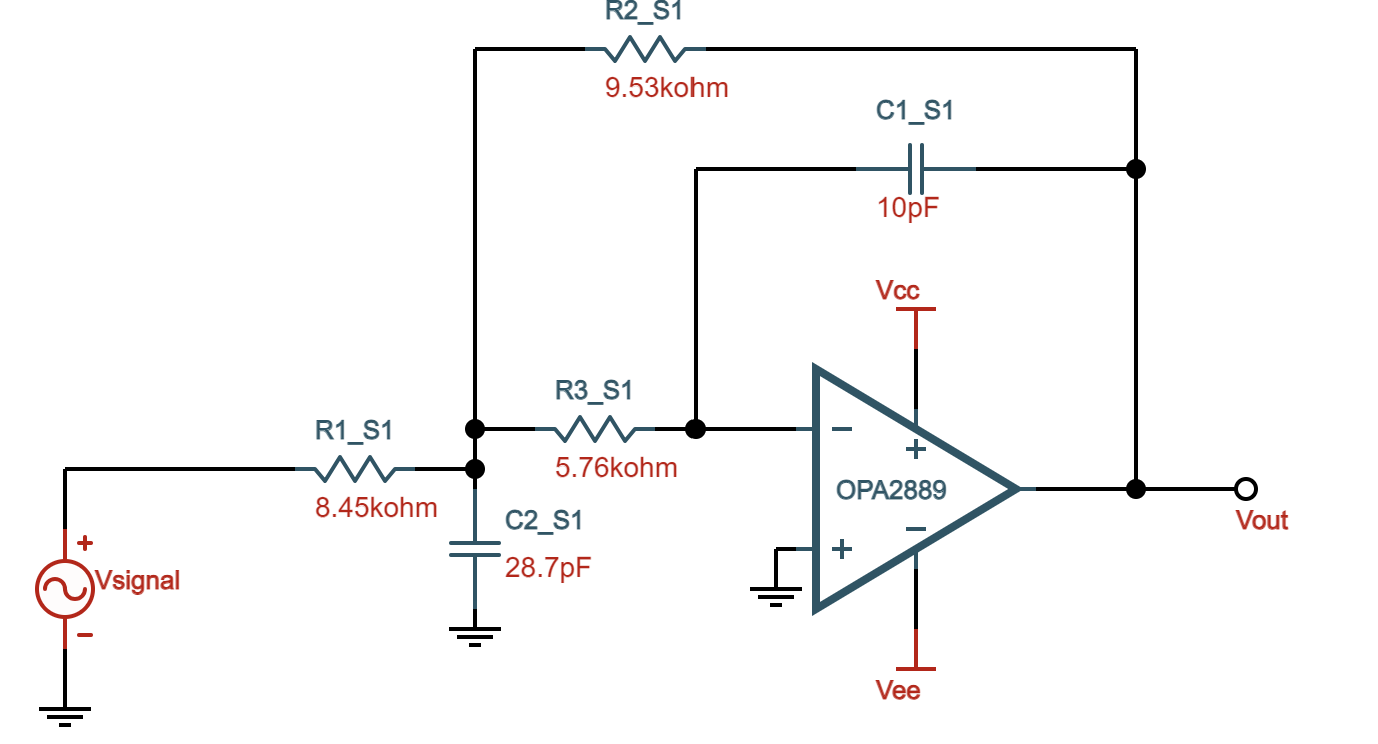
A 2-pole passive RC filter is almost as good (for many applications) as a 2-pole active filter. If you really expected to see extreme noise without digital filtering, you could set your cutoff at 24kHz, with a 2-pole filter to get -76dB at Nyquist (this would be extreme overkill, I suspect).
You mentioned in your application you are sensing suspension pots. Generally, vehicle suspension response is in the single-digit to the low double-digit range, so sampling at one or two ksps with a 15 or 20Hz single pole filter should be just fine.
Additional Notes
Delta-sigma ADCs sample at a very high frequency, generally with a 1-bit ADC many times the Output Data Rate (ODR); loosely delta-sigma ADCs work by filtering a high bandwidth single-bit ADC to produce a low bandwidth many-bit outputs.
This means you only need to provide anti-aliasing filtering to meet the Nyquist frequency of the sample rate, greatly relaxing the filtering requirements.


