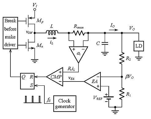
I am studying a peak current-mode controller, and here is the schematic without slope compensation:
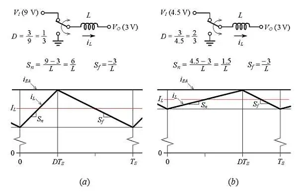
Before introducing RSENSE to the design, I understood that if feedback voltage increases, it is compared with a constant VREF to determine to do what with switches. According to the information from the site, the switches are reset when Ri · iL = VEA, indicating that iL can't exceed IEA.
I am encountering difficulties in understanding:
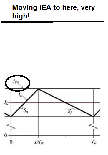
- In many designs, RSENSE is selected in a way that iL never reaches IEA. For instance, when I simulate the circuit using LTspice and choose a smaller value for RSENSE, it always operates without issues. However, problems arise when I opt for a larger resistor value, leading to current limiting through the inductor. I am confused about what actually triggers the switches to turn ON/OFF if IEA is picked to be very high. What is going to limit iL then?
- The schematic (figure 1) suggests that the switches are reset when Ri · iL > VEA. However, I am puzzled by datasheets such as the one for the LT3890, which consistently mention a fixed sensing voltage, in this case, 50 mV. I am uncertain about the role of this fixed sensing voltage in the comparator. My understanding is limited to the idea that if the sensed voltage exceeds 50 mV, the switches turn off, but I am unsure how this concept aligns with the schematic above.


