0
\$\begingroup\$

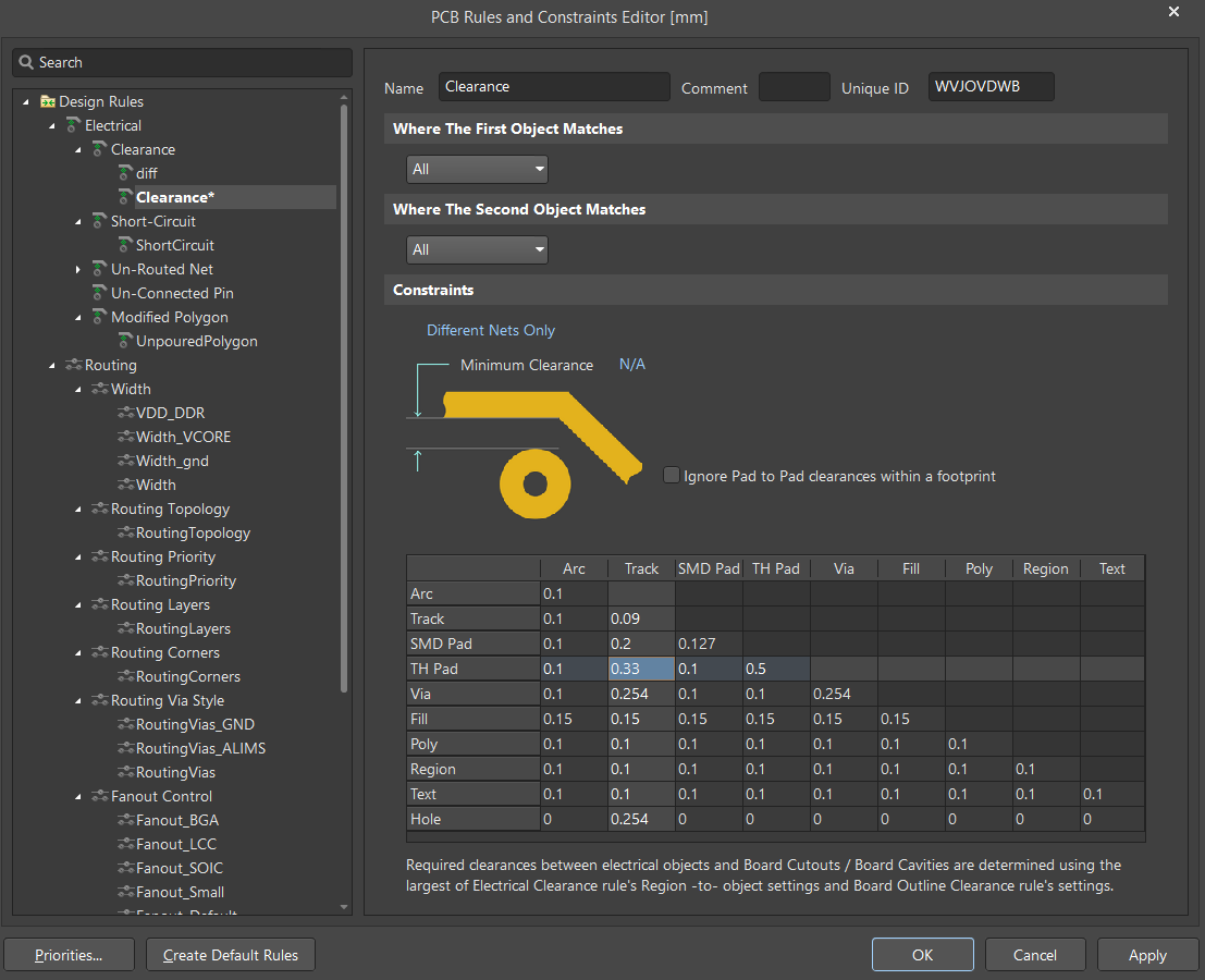
What is the right design rules from JLCPCB? When I look at the electrical clearance from JLCPCB, I find:

  • Via to Via (Same net labels): 0.254mm
  • Hole to hole (Different net labels): 0.5mm
  • Pad to pad (Different net labels): 0.127mm
  • Pad to Pad with hole (Different net labels): 0.5mm
  • Via to track: 0.254 mm
  • Plated Hole to track: 0.33mm
  • Non Plated Hole to track: 0.254mm
  • Pad to track: 0.2mm
  • Minimum spacning: 0.09mm (4-6 layers)

https://jlcpcb.com/capabilities/pcb-capabilities

Question:

Are these the correct settings of the design rules?

enter image description here

Issue:

The issue is that it seems like a regular BGA footprint cannot even be produced by JLCPCB with those design rules. I have downloaded a sample CAD model from STMicroelectronics and it seems that all the rules from that model violate the JLCPCB rules. Is that correct?

\$\endgroup\$
3
  • \$\begingroup\$ are you entering the parameters in the correct units? \$\endgroup\$ Commented May 2 at 23:00
  • \$\begingroup\$ @JasenСлаваУкраїні yes, in mm. \$\endgroup\$
    – euraad
    Commented May 4 at 11:09
  • \$\begingroup\$ You would stand a better chance of getting a good answer if you included an image the proposed BGA footprint. I don't think anyone is going to go to a registration-walled site and install a footprint just to answer this question. \$\endgroup\$ Commented May 4 at 22:19

1 Answer 1

0
\$\begingroup\$

Yes!

The answer is that JLCPCB can produce that CAD-model. I uploaded the gerber files of that CAD-model and load it into JLCPCB and ask them for review the gerber files.

Approved, from their side.

\$\endgroup\$

Your Answer

By clicking “Post Your Answer”, you agree to our terms of service and acknowledge you have read our privacy policy.

Not the answer you're looking for? Browse other questions tagged or ask your own question.