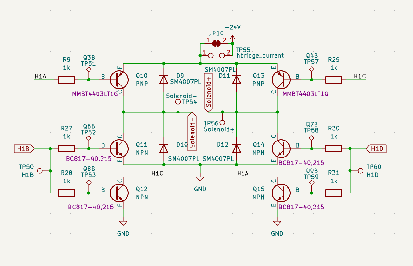
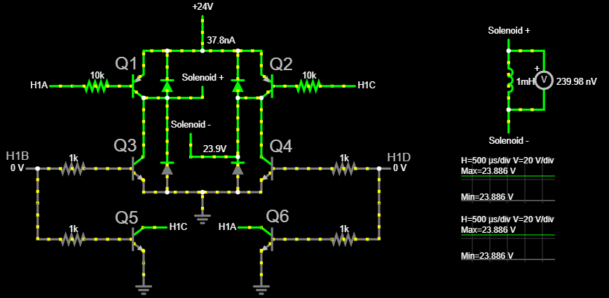
I am working on controlling a bi-stable latching solenoid with an H-bridge.
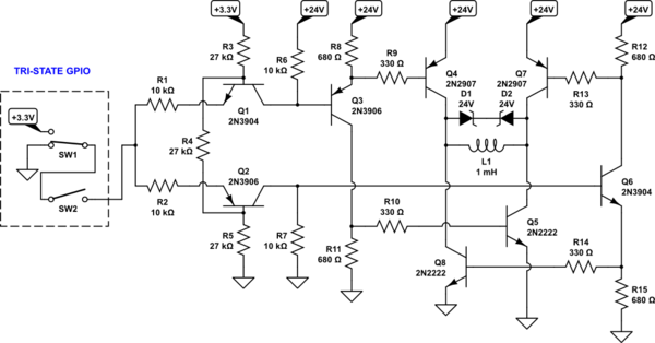
The microcontroller that I am using for my project doesn't have enough GPIOs for me to use four pins for the H-bridge, so I designed a circuit with PNP and NPN transistors:
I tested the circuit in simulation before making my board and it appeared to work. Setting H1B to high set the direction of the voltage correctly and vice versa.
I built my PCB and discovered that when 24 V is applied to the power rail, my power supply goes into constant current mode (even when H1D and H1B are both at 0 V). I added some control to the H1D and H1B lines but can't get either of them to close Q13 or Q10.
What could be causing this to short with H1D and H1B both low? Do you see any issues with this circuit?
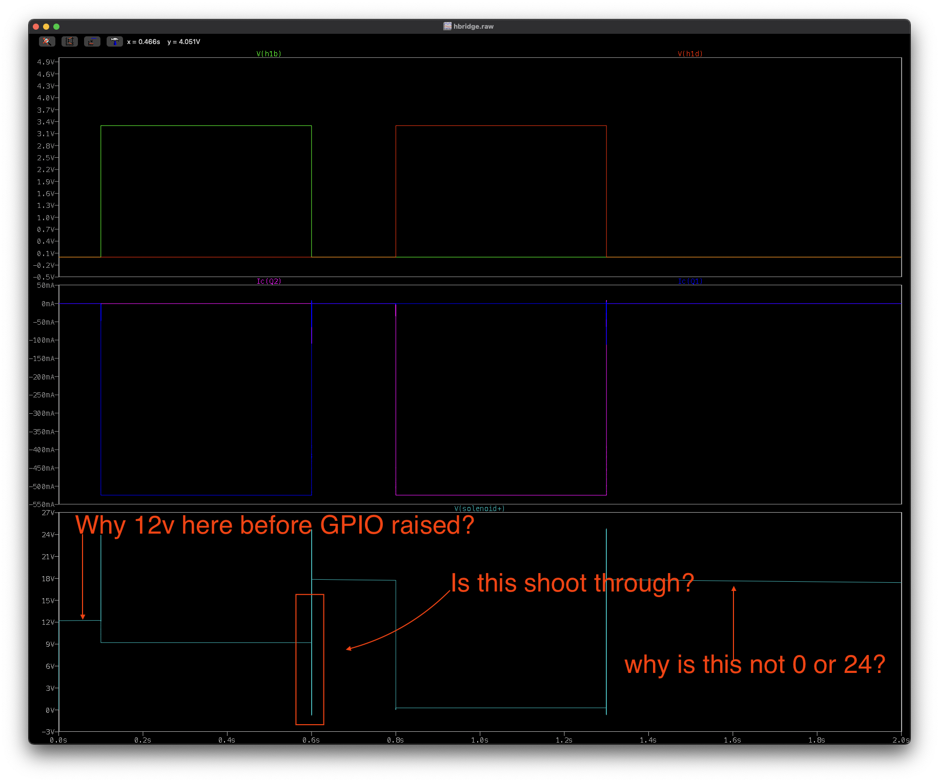
Latest Simulation
I rebuilt the model in LTspice to get more accurate component models. I am seeing some strange behavior. The solenoid+ is seeing 12 V before any FETs are opened. How would that happen? I also moved the PNP resistors to below the NPN so that they don't pull any current and activate PNP. Changing the diodes to VS-E5TH1506 fast-recovery diodes helped bring the end voltage back to 12 V.

