First off, I would like to stress the fact that I am no electrical engineer or anything of the sort, just a hobbyist that is into this kind of stuff. So please bear with me, as I know a few things about electronics but am still heavily learning a lot of things. I normally just research my inquiries myself until I find the solution(s), but in this case, due to the inherent danger involved in using 18650 battery-packs, I need to be absolutely certain before moving forward with this project.
The project is a custom made Bluetooth and audio box, using the following bluetooth front panel module (2*25w), combined with a 3S2P 18650 battery to provide the 12v required:
https://nl.aliexpress.com/item/1005005792726449.html
The battery combines 6 3200mah INR18650-33V batteries, they have a discharge-rate of 10A and a charge-rate of 0.5C. The bluetooth 2*25w amp draws a current between 1-3A and requires 6-12v, ideally 12v, to be fully powered. So in any case, a 12.6v 3S BMS of about 10A would more than suffice.
But these batteries require a special charger that provides CC-CV charging and balancing and for all intents and purposes, I would find it cumbersome to always have to carry a dedicated charger while having dozens of 12v chargers lying around the house with which I'm used to charge all my 12v devices.
The snag I'm bumping into is, of course, finding a way to use a normal AC/DC charger while still safely charging the 3S2P battery pack without burning down the roof of my house. And before everyone automatically starts stating that I do need a special charger without exception, I've already found out that it is actually doable in a few different ways, but it does involve some effort, knowledge and skills.
As I've been researching these past days, I came upon a few different ways mentioned online and used by others. Some suggest to just add a cheap 3S 12.6v 10A BMS from aliexpress and solder a dc socket to the in-output. Then just go ahead and use a normal AC/DC power adapter but make sure you never let the batteries charge more than 4.1v. Apparently, ppl actually do this but of course, this turns out to be very unsafe and bad for the batteries, the BMS, the entire electronic circuit and even your entire house since you're prone to cause a fire and burn it to the ground. There is no balancing and the BMS is designed to work together with a balance-charging device that supports the CC-CV method. Using this dubious method will make them prone to overheating, swelling and exploding, even when using a power supply with correct current and voltage. So shortly after I initially discovered this method being used, I found out that it is a very bad idea. Option one was thereby crossed-out pretty fast. This would be ill-advised in any circumstance.
Then I found out that you can use a BMS module with a USB-C boost charge module, that converts the 5v from the usb to the required 12.6v, but ultimately the current is very low and charging would be very slow. Moreover, this still does not provide proper CC-CV charging and balancing, only a boost-conversion between the USB-connection and the BMS. This too turns out to be not worth it even though again, many ppl actually do just wire this boost module to the BMS and just charge via USB-C without additional protection or balancing. But even with proper balancing and CCCV, the charging would be too slow and inefficient, so no go for me in either case.
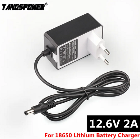
Then I found out that aliexpress also sells CC-CV chargers for 18650 Lithium-Polymer batteries with a normal DC plug, to be used in a normal DC socket:
https://nl.aliexpress.com/item/4000878939756.html
They have the proper voltage and since my 3500mah batteries have a discharge-rate of 0.5C, 2A would seem like a sweet-spot between 0.5-1C, ensuring to not exceed 1C, just to be gentle on their wear and tear.
So technically, these could be used with a DC socket soldered to the BMS P+P- input and such would be ideal as it is exactly what I'm looking for. Though the absurdly translated descriptions on aliexpress are very unclear whether these chargers internally offer the required protections and balancing, although they are CC-CV chargers... So I am unclear whether they still require additional balancing and/or protection in the battery-circuitry. My educated guess though says they most likely do. Additionally, I do not really trust these cheaper chargers (they only cost a few bucks) and some have reported them becoming very hot. It seems that they work but they get extremely hot, by one reviewer mentioned "terrifyingly hot". Does not spur any confidence so in any case, against my desire for this seemingly easy solution, this is likely another cross-out.
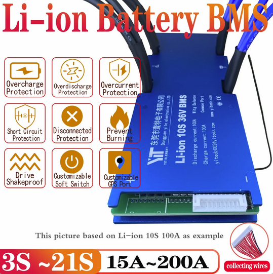
Then, finally, I came upon the following BMS with overcurrent protection, overcharge- and overdischarge protection, short-circuit protection, disconnection protection, temperature monitor and fire prevention option, AND balancing for each of the three series of batteries:
https://nl.aliexpress.com/item/1005004417136992.html
It is noticeably more expensive at almost 20 euros, and a brief communication with the seller taught me that this module provides passive balancing while they also have an even more expensive active balancing "smart" module that costs no less that 75 euros, and that the passive option is more suited for batteries with very good consistency and performance and the active alternative provides the most optimal safety for even the most unbalanced or degraded cells.
But since my batteries are brand new with large 3200mah capacity with 10A discharge-rating and they are all at almost perfectly the same voltage-level, I would guess that the passive option would indeed be more than sufficient for my needs. Also, the load (=bluetooth amp) will never exceed 3A so they will not be used for very high current-draws at all.
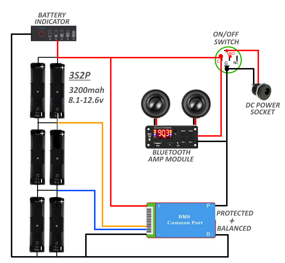
So, question, while ignoring all previously crossed-out options, will this be a proper BMS module that allows me to wire a DC socket to its input and use a 12v power supply to charge the batteries? They would be protected and balanced so I see no issues with this option. It would all be wired as following, pls do tell me if there are any mistakes in the diagram. It's a simple diagram but it works for me...
I could additionally add the USB-C boost charge module to this to have it as a secondary power source if none other are available, that way it could be charged in all circumstances. This would have the best of both worlds if it works.
But as said, I'm not that electrically savvy, and I have to be sure that I'm not going to null my fire insurance :p Any suggestions or improvements (though not too complicated) would be massively appreciated. Last resort would be to just use DC alone without battery, or go with another type of batteries, but I hope it won't be necessary.


