How is the EMF induced in the coil?
First let's answer the question of what EMF would be induced by a magnetic field in the absence of any conductors
To do so, we will define an electric vector potential \$\vec{W}\$ and associated electric scalar potential \$\phi\$ as fields satisfying the two equations:
$$\vec{E} =-\nabla \phi + \nabla\times\vec{W}$$
$$\nabla\cdot\vec{W}=0$$
Now
$$\nabla\times\vec{E} = \nabla\times(-\nabla U)+\nabla\times(\nabla\times\vec{W})$$
but the curl of a gradient is \$0\$, so
$$\nabla\times\vec{E} = \nabla\times(\nabla\times\vec{W})$$
$$\nabla\times\vec{E} = \nabla(\nabla\cdot\vec{W})-\nabla^2\vec{W}$$
But since $$\nabla \cdot \vec{W}=0$$,
$$\nabla\times\vec{E} = -\nabla^2\vec{W}$$
Maxwell's version of Faraday's Law (in vector notation) says
$$\nabla\times\vec{E} = - \frac{\partial\vec{B}}{\partial t}$$
so
$$\nabla^2\vec{W} =\frac{\partial\vec{B}}{\partial t}$$
This is a Poisson equation, with solution:
$$\vec{W}(r)=\frac{1}{4\pi}\int_{R^3}\frac{\partial\vec{B}(r')}{\partial t}\frac{1}{|r-r'|}d^3r'$$
Define
$$\vec{E}_{\partial\vec{B}/\partial t} = \nabla\times\vec{W}$$
The emf induced along some curve \$C\$ from \$a\$ to \$b\$ is
$$\mathscr{E}_{\partial\vec{B}/\partial t} = \int_{C:a\rightarrow b} \vec{E}_{\partial\vec{B}/\partial t} \cdot d\vec{s}$$
Note that this emf is path-dependent.
Now, if we add a conductor to the system, which conductor lies along curve \$C\$, but possibly extends beyond \$C\$, we will still have the same emf induced as before. But the electric field inside a conductor is governed by the microscopic version of Ohm's Law:
$$\vec{E} = \sigma\vec{J}$$
The time-varying magnetic field wants to induce an electric field \$\vec{E}_{\partial\vec{B}/\partial t}\$, but the conductor insists on \$\vec{E} = \sigma\vec{J}\$. To reconcile these fields, a surface charge develops on the surface of the conductor. This surface charge ensures that, within the conductor, the microscopic version of Ohm's Law is obeyed.
If the conductor does not form a complete circuit, then there will be no steady-state current, and hence no steady state \$\vec{E}\$ field within the conductor. In that case, the surface charge completely cancels the \$\vec{E}_{\partial\vec{B}/\partial t}\$ field within the conductor, but creates a conservative \$\vec{E}\$ field external to the conductor. This reaction field creates a potential difference between one end of the conductor and the other, even though the ends may be far away from where the time-varying magnetic field is directly acting upon the conductor.
If the conductor does form a closed loop, or is part of a completed circuit, with perhaps other components such as resistors, then current will flow in the conductor. The surface charge doesn't exactly cancel the \$\vec{E}_{\partial\vec{B}/\partial t}\$ field within the conductor, but leaves enough \$\vec{E}\$ field to permit a current to flow within the circuit. However, like in the open-circuit case, the surface charge creates voltage drops that may be far away from the location where the time-varying magnetic field is directly acting upon conductor. For example, if circuit consists of only the conductor and a resistor, and the resistance of the conductor is very small, virtually all of the voltage drop corresponding to the induced emf will appear across the resistor, even though that resistor may be far from where the time-varying magnetic field directly acts upon the conductor.
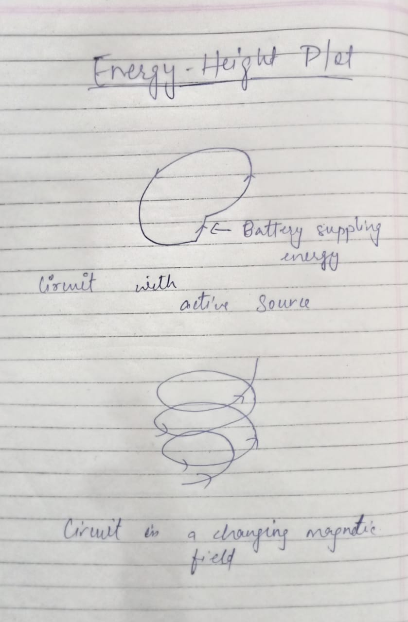
I now wish to address your "energy-height" diagram.
Electrons have a net drift, i.e. a current, in an ordinary conductor because there is an electric field accelerating them in a particular direction. However, they only drift for a short distance before they collide with other things, and their motion becomes randomized. Thus, the electric field must be present all along the conductor for current to flow all along the conductor.
Your circuit is driven by a time-varying magnetic field, which generates an electric field (which has further consequences). It does not, however, contain any batteries or other possible sources of emf that might cause charges to migrate against an electric field. Using the analogy of altitude as a substitute for electric potential, your circuit has no ski-lifts.
As a result, the only way current can flow in such a circuit is for there to be a circulating electric field. The electric field in within the conductor is not conservative, and cannot be conservative, or there would be no current.
You wrote:
I agree that there is no such term as EMF in a non-conservative field
I'm not exactly sure how to interpret what you wrote, but it is most definitely the case that non-conservative nature of the electric field in your example (which lacks a battery, etc.) provides the only reason there is current.
Now the force that acts on charges as they flow around the circuit performs work on those charges. But the net work done on charges around the loop does not (for long) raise their energy level. The charges, while traversing the loop, collide with other things and convert the potential energy that they gained into heat. If an electron were to travel around the loop (in a short enough time period that we can ignore changes in the electric field), it would have the same "energy level" when it arrived at it's original starting point, as it did when it first left that starting point. The sum of the changes in potential, as one goes around the loop total zero. There is no spiral, as in your diagram.
Your confusion probably stems from assuming the change in "energy level" between two points can be found by finding the line integral of the electric field, i.e.
$$\int_{C:a\rightarrow b}\vec{E}\cdot d\vec{s}$$
But that is the work done on the charges as they move along the line from \$a\$ to \$b\$.
If we subtract the emf induced along a line from the work done on a unit charge as it moves along that line, we will find the change in potential energy.
$$\Delta \phi = \int_{C:a\rightarrow b}\vec{E}\cdot d\vec{s} - \int_{C:a\rightarrow b}\vec{E}_{\partial\vec{B}/\partial t}\cdot d\vec{s}$$
which turns out to be the same as
$$\Delta \phi=\int_a^b \left(\nabla\frac{1}{4\pi}\int_{R^3}\frac{-\rho(r')}{\epsilon_0}\frac{1}{|r-r'|}d^3r'\right)\cdot d\vec{s}$$
and that latter integral, when C is a closed loop, evaluates to 0 by the gradient theorem. That is, there is no "spiral" in the "energy height" diagram.

