2
\$\begingroup\$

I want to design a low power H-bridge on bipolar transistors. I've already made one, built the board and tested it. Generally works, but there are difficulties with control and sometimes I have a short circuit in the power supply.Here is the first version I made: First H-bridge
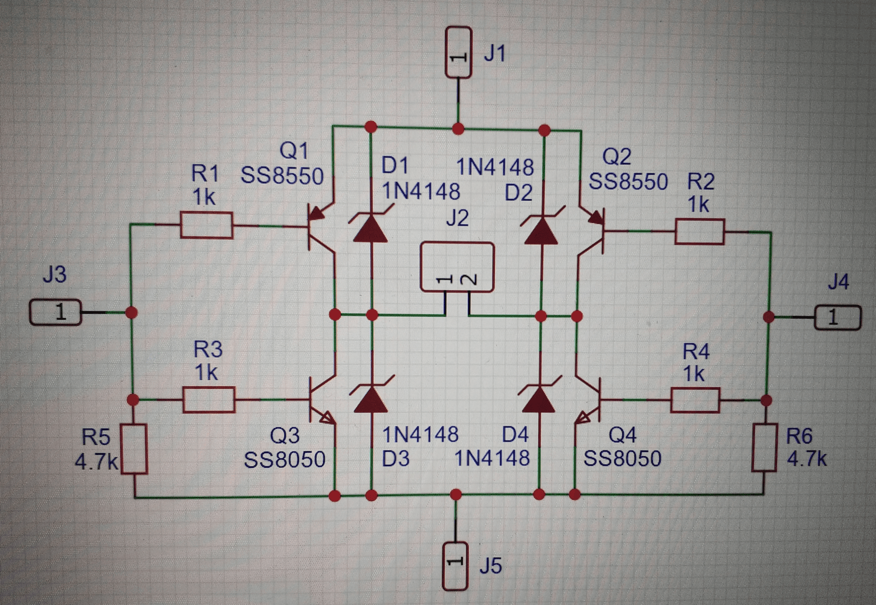
Now I found another scheme, and I plan to use it: H-Bridge Transistor Smoking (Bipolar BJT Transistor)

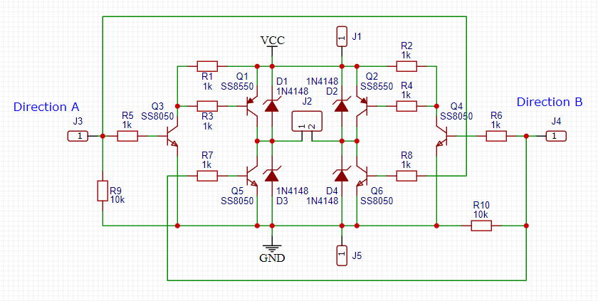
I changed my design a bit based on the post above: My new design of H-bridge I combined the control inputs in pairs. Thus, the upper and lower transistors cannot be opened at the same time. Although I'm sure it will work, but what would you say to this? My control inputs may not be connected anywhere and catch interference. Therefore, I added two pull-up resistors to ground, so that at least the bottom transistors are closed and there is no short circuit. The upper transistors will be open all the time. What do you think of my design? Maybe they would give some advice. Thank you
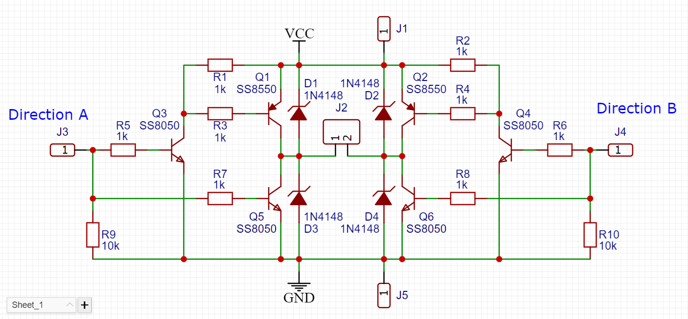
I changed my previous design a bit, should be correct. Redesign
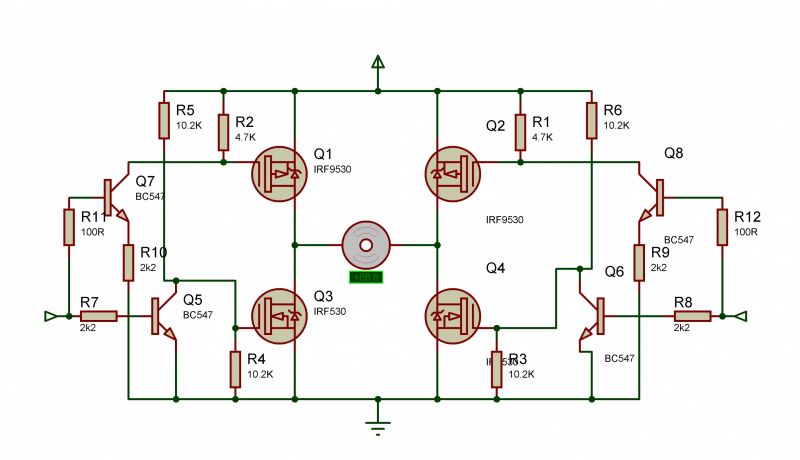
And what about such a scheme? Instead of mosfet transistors, I use bipolar ones. I want to find a circuit that will not have dangerous input combinations and will not react to unconnected control inputs. Scheme from radiokot
\$\endgroup\$
4
  • 2
    \$\begingroup\$ I think something may be lost in translation -- we usually mean "open" for a low-current (open-circuit or broken connection) state, and "closed" for a low-voltage (closed-circuit or shorted) state. This makes your question sound inconsistent (though I think I still have understood what you're saying). We also say "pull-down" when it's a resistor to GND. Could you rephrase it for better clarity? \$\endgroup\$ Commented May 26 at 23:39
  • \$\begingroup\$ I may be missing something here, but in your second schematic, if you drive J3 high, doesn't that turn on Q3, Q5 and Q1 all at the same time? Normally with this kind of circuit, you'd connect the base of Q3 to J4 and the base of Q4 to J3. \$\endgroup\$
    – Dave Tweed
    Commented May 27 at 4:14
  • \$\begingroup\$ OK, i see. I meant that open is when it conducts current. And closed - does not conduct current. I was wrong here. The translator also replaced the pull-down resistor with a pull-up. Now I can see that if I apply a logic one to J3, both transistors Q1 and Q5 will conduct and I will get a short circuit. I want to merge together the bases on the left side. And also on the right side. That way I never get a short circuit at any levels on the control inputs. For this I have to connect the base of Q3 to J4 and the base of Q4 to J3. Right? \$\endgroup\$
    – Rodney
    Commented May 27 at 7:36
  • \$\begingroup\$ Your final circuit will work with one caveat when switching: both sides inputs must be held low before changing states. As an example, if you start with J3 high and J4 low, you must first pull J3 low and allow some dead time before driving J4 high. Otherwise, you will have "shoot through" with Q1, Q2, Q5, and Q6 all on at the same time, \$\endgroup\$ Commented May 27 at 17:55

1 Answer 1

1
\$\begingroup\$

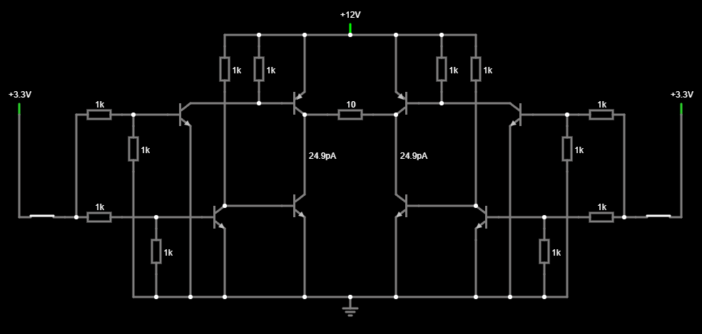
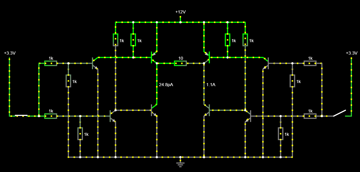
Now I settled on a new scheme that I plan to exploit. I tested it in the online simulator, it should work in practice. As I wanted, the circuit does not have dangerous combinations that will lead to a shoot through. Floating control inputs will not cause problems. The only thing that confuses me is that the number of transistors is twice as large, and the huge number of resistors. The resistor ratings on the circuit are still standard from the simulator, but it already works well. Perhaps someone knows of other circuits that do not contain such a combination that will lead to a short circuit and use fewer transistors. 8vt-h-bridge-1 8vt-h-bridge-2

\$\endgroup\$

Your Answer

By clicking “Post Your Answer”, you agree to our terms of service and acknowledge you have read our privacy policy.

Not the answer you're looking for? Browse other questions tagged or ask your own question.