4
\$\begingroup\$

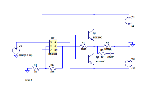
I have tried to import a third party model from TI, to be precise the op-amp A551. And somehow my circuite, a power amplifier, gives me the following error.

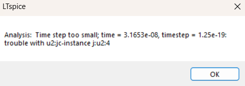
enter image description here

Analysis: Time step too small; time = 3.1653e-08, timestep = 1.25e-19: trouble with u2:jc-instance j:u2:4

It seems like my transient analsys is trying to hit a level of precision it just cant handle. The thirt party model was probably implemented correctly (I could be wrong), but why than doesnt the transient analsys work.

enter image description here

enter image description here

\$\endgroup\$

4 Answers 4

5
\$\begingroup\$

I see 3 mistakes you should correct before complaining about the op-amp model:

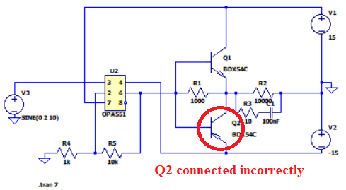
  1. Reverse the emitter of the BDX54C PNP.
  2. U2 is wired up as a non-inverting amplifier. This amplifier can provide a well-defined output voltage provided that it can drive the load. However, Q1 and Q2 with its resistor are wired as a transimpedance without much loop gain. They way you've wired it makes no sense. You probably meant to wire it @csabahu did it. The darlington stages provides drive capability to the amplifier and both of them must be within the feedback loop.
  3. most importantly, your op-amp doesn't have any net supply voltages, as V2 is effectively +15V with respect to ground. Remove that (-) sign from the "-15" value of V2 or flip V2 such that the (+) sign is looking downwards. Your op-amp is right now, therefore, receiving +15V in both positive and negative supply pins.
\$\endgroup\$
3
  • \$\begingroup\$ Ooof. Brutal, but fair. \$\endgroup\$
    – Ste Kulov
    Commented May 28 at 5:48
  • 1
    \$\begingroup\$ @SteKulov didn't mean to be brutal, just giving some honest feedback :) \$\endgroup\$
    – Designalog
    Commented May 28 at 6:07
  • 1
    \$\begingroup\$ Haha. I know. I agree. \$\endgroup\$
    – Ste Kulov
    Commented May 28 at 6:41
3
\$\begingroup\$

Try fixing this first: -

enter image description here

Also note that some models are a bit flakey and sometimes you have to change the calculation engine or precision settings.

\$\endgroup\$
3
\$\begingroup\$

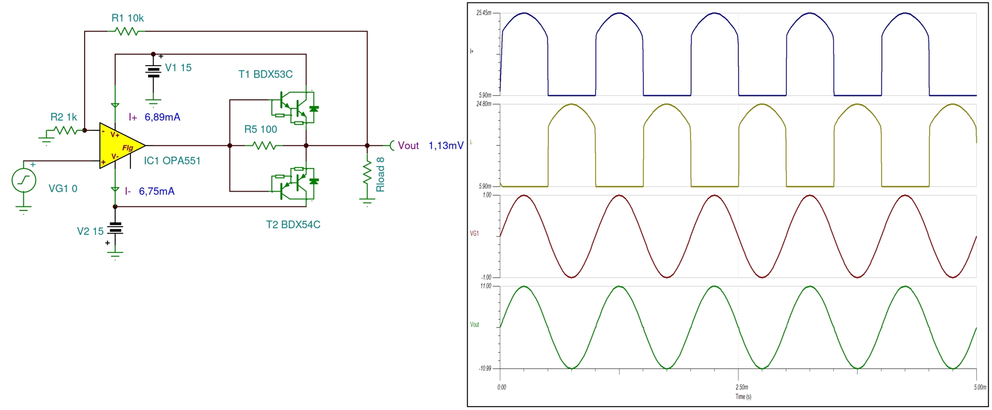
The factory model of the amplifier works fine. You have both transistors identical (BDX54C), this is probably a mistake. The wiring of the lower transistor is also faulty. I think you wanted to do something similar to the schematic below: enter image description here In the schematic, the DC values are measured without an input signal.

I hope this will help.

\$\endgroup\$
2
\$\begingroup\$

First you need to flip the collector and emitter on the bottom transistor for the circuit to work, but often times you will get this error if there is some very high frequency oscillations in the circuit. The simulator will try to reduce the step size further and further to solve for this, but gives up at a certain point if the time step is too small. This can usually be solved by adding some capacitance to your circuit.

Failing that, a trick that might work (in LTSpice anyway) is to add the directive below. This adds the specified amount of capacitance to every node in your circuit (10pF) in this case.

.options cshunt 10p

\$\endgroup\$
2
  • \$\begingroup\$ I believe it’s .options cshunt=10p ??? \$\endgroup\$
    – Ste Kulov
    Commented May 28 at 5:47
  • \$\begingroup\$ @ste-kulov you are correct. I updated the response. \$\endgroup\$ Commented May 29 at 13:41

Your Answer

By clicking “Post Your Answer”, you agree to our terms of service and acknowledge you have read our privacy policy.

Not the answer you're looking for? Browse other questions tagged or ask your own question.