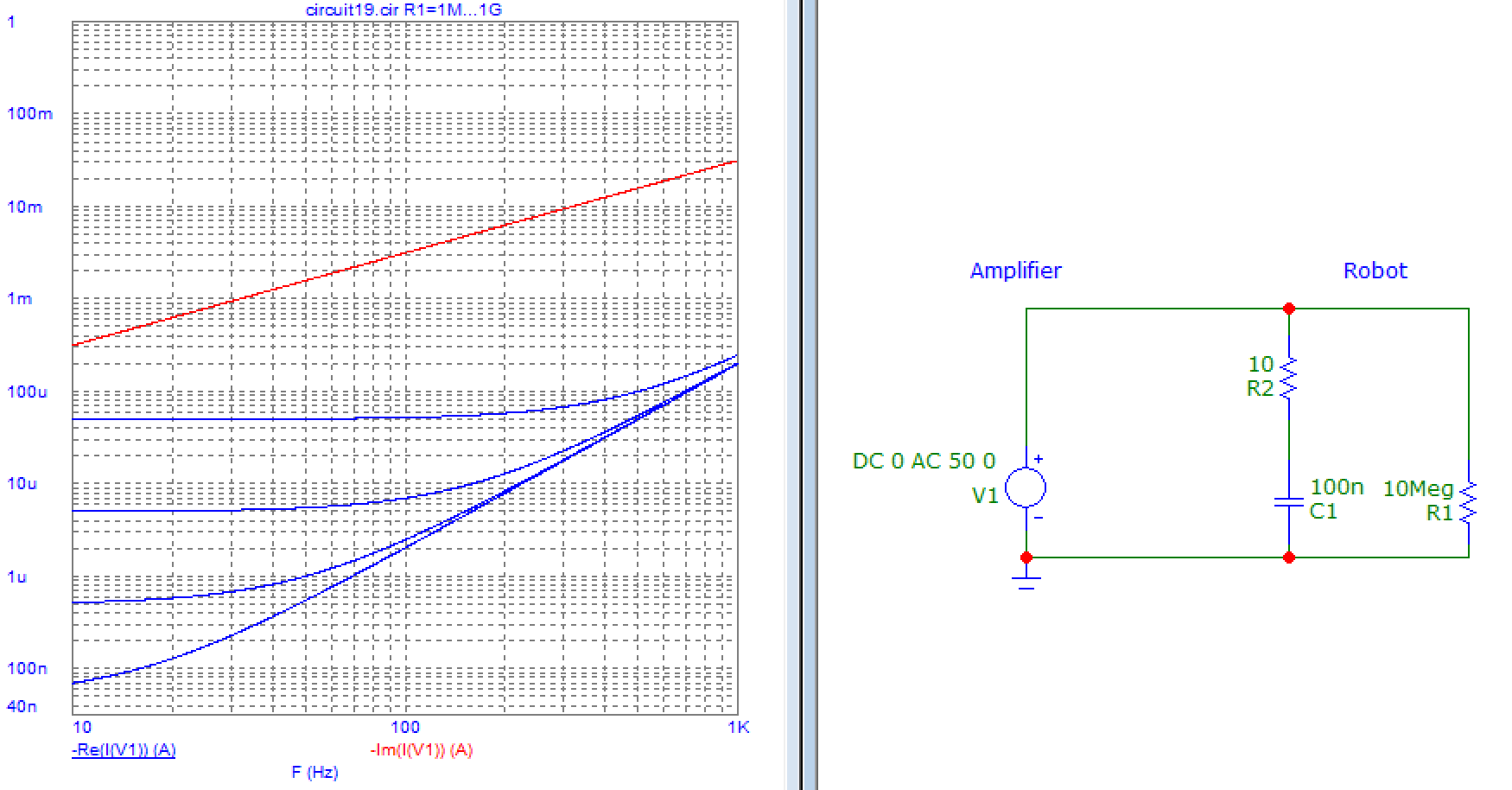
On our subsea robot, we have an isolated power supply (converting 3-phase AC into 320 Vdc).
For security reasons, we have a line monitor monitoring the resistance between protective earth and both 0 V and 320 Vdc voltage rails. Some equipment have their carcass connected to protective earth. In normal operations, the resistance between earth and 0 V or earth and 320 Vdc is supposed to be >20 MΩ (the maximum value the line monitor can measure).
From time to time, we have some small leakage (resistance in the 100 kΩ - 19 MΩ range).
For now, to find the fault, we just plus/unplug things to try to find out where the fault is. Sometimes it works well, but sometimes it takes a lot of time, especially when it is in some unexpected place (at those levels of sensitivity, some materials that look like isolators are just big resistors, dust and humidity starts to matter, ...).
The way the line monitor works is by injecting generating a +-50 Vdc voltage between earth and either 0 Vdc or 320 Vdc for 2 seconds, and measuring the resulting current (20 MΩ = 2.5 µA).
My question is: is there any efficient way to track down where the fault is? (The fault might be in the wiring, on a PCB (custom design or of the shelf), or in a black box device (like a motor)).
Also note that in most cases, the fault is also present when the power supply is turned off, so methods working only when only the line monitor is active are also welcome (most diagnostics are done this way, as it avoids working with 320 Vdc present nearby).
Test equipment available: scope, isolated scope (battery powered), multi meters (including one with µA range), lab power supplies (up to >500 V), mega-ohm-meter (injecting 250 Vdc or 500 Vdc, measuring resistance up to 10 GΩ), function generator, programmable load, current clamp down to 10 mA dc. If you have a solution requiring some other equipment, feel free to suggest, I might be able to convince the CTO to buy it.
Solutions working only for the bigger leakages (resistance <2 MΩ) are also of interest.

