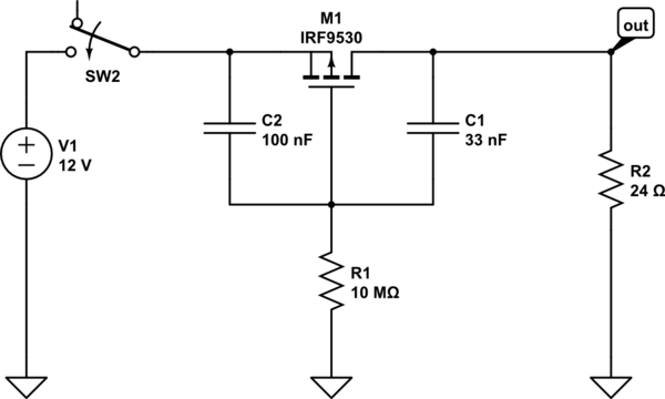
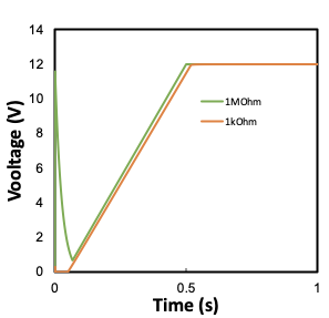
I am trying to design a soft-start circuit for one of my projects which has a relatively large resistive load (~1MOhm). I found the following example circuit from an answer for a previous post (12 V Soft-Start circuit) which works well for a low resistance load (24 Ohm):
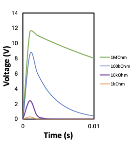
However when I subsequently increase the load resistance (R2) beyond 1kOhm there begins to be a noticeable initial voltage through R2 which becomes very significant at the load resistances I am interested in (simulated in CircuitLab with a 1ms step size).
While the soft-start behavior is maintained, the voltage spike is not compatible for my application.
I would like to find an explanation for this behavior and be able to eliminate it in an updated circuit design. My initial thoughts are that even for the initially low resistive load such a 'spike' is still present, but its magnitude and length are so small it doesn't show up in the simulations. Perhaps this is due to an initial time constant associated with the RC section C1 and R2. However, attempts to lower C1 and subsequently adjust the values for C2 and R1 lead to significantly decreased soft-start ramp times (undesirable).
My current understanding of how this circuit functions is that the values of C2 and C1 need to be appropriately sizes to have Vgd less than the threshold value (here Vt = 3.3V). The time constant of the soft-start is set by R1 and the series capacitance of C2 and C1 (approx. C2R1 minus C1R1). The apparent time constant of the initial voltage spike (when R2 is increased beyond approx. 1kOhm) appears to be proportional to C1*R2. It is unclear to me how the component sizes are affecting the magnitude of the voltage spike however. The simulations show that the gate voltage experiences a similar spike when the switch is closed as well. Any advice and input would be greatly appreciated.


