1
\$\begingroup\$

enter image description here

I am very new to electronics and electrical design, so please be nice. This is probably a dumb question to people more knowledgeable than me in the subject, but I'm just wanting/trying to learn. I've never used any kinda forum before, so I'm sorry if I posted this in the wrong place.

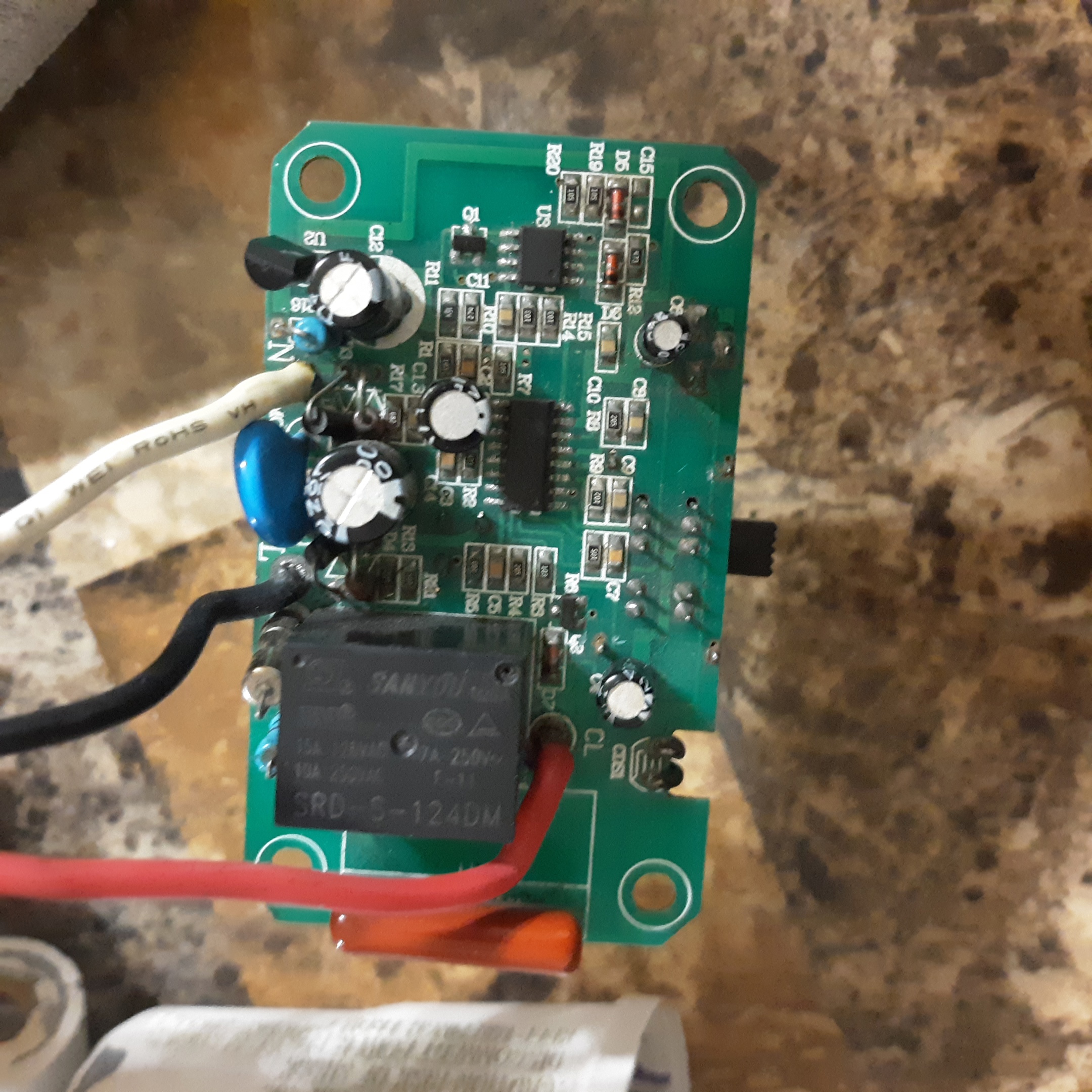
My question pertains to a PCB which is for a motion activated floodlight, I don't know if that's even relevant because I'm sure there's a common reason for this, but I just don't know what it is. This circuit has the standard American 3 prong grounded plug. The black wire is hot, white is neutral, the green is ground. The green wire is obviously connected to the metal part of the fixture for safety. The white wire has a wire nut junction where it connects the return wires from each bulb, then the white wire continues on to the PCB. The black wire goes straight to the PCB.

The little PCB houses the motion sensor, daytime awareness sensor (don't know the real name of it) and the relay which turns the light bulbs off and on when motion is detected. There's only one wire coming out from the PCB, it is a red wire that is the line out to carry power to the bulbs. The red wire comes to a wire nut connection, which splits it to each bulb, to enable both bulbs to get powered at the same time. On the other side of the load (bulb), the wire is white and is the connection I spoke of earlier that ties into the original white wire coming in. Sorry if this doesn't make any sense.

The question I have is, why is there a neutral in that goes to the PCB, but not a neutral out from the PCB to connect to the bulbs?
Or another way to word it, why does the neutral split before the PCB and go out to the bulbs?

I know why the power doesn't and couldn't, because it needs the PCB to manipulate the circuit for power on and off.

  • Could the neutral have been ran thru and out of the PCB and then split off to the lights?

  • Is the neutral sort of being a “ground” for the PCB?

  • Is this a common design?

I just assumed since the power was going through the bulbs, the neutral would need to just be on the other side of the load for a return path.

  • What power would/could return from the board through that neutral, instead of going on and out through the bulb?

  • Is the neutral connected to the PCB so when the relay is NOT active there's still a return path? Is this a something to do with safety?

Sorry for so many questions. Anything electrical just intrigues me and I really want to understand. I've tried to look this up on other sites, but I couldn't find anything close enough to what I was referring to get a definite correct answer. Sorry once again if this is really dumb. I'm just learning. Thank you in advance to anyone who can shed some light on this for me (pun intended). 😁

\$\endgroup\$
6
  • \$\begingroup\$ Welcome! A picture would be worth a thousand words here. \$\endgroup\$
    – winny
    Commented Jun 7 at 10:49
  • \$\begingroup\$ I've never used any kinda forum before how do I add a picture? \$\endgroup\$ Commented Jun 7 at 10:50
  • \$\begingroup\$ Click on edit, then the picture symbol. \$\endgroup\$
    – winny
    Commented Jun 7 at 10:51
  • \$\begingroup\$ Ok I'll try. I couldn't even figure out how to make my question into paragraphs. Lol. But looks like someone really nice did that for me somehow. Thank you to whoever did that, it's much easier to read now. \$\endgroup\$ Commented Jun 7 at 10:54
  • \$\begingroup\$ I think I added a picture. Can you add more than one picture? \$\endgroup\$ Commented Jun 7 at 11:15

3 Answers 3

2
\$\begingroup\$

Neutral is common between the input and output side. In other words, there are no components that need to be in series with the neutral line between input and output. Therefore, it is more reliable to make only a single connection to the PCB, which needs a connection to neutral for its circuit.

\$\endgroup\$
3
  • \$\begingroup\$ Thank you for answering my question. \$\endgroup\$ Commented Jun 7 at 11:13
  • \$\begingroup\$ Is it more reliable or just simpler or cheaper? \$\endgroup\$ Commented Jun 7 at 11:20
  • \$\begingroup\$ Both, but it is more simpler and cheaper than it is more reliable. \$\endgroup\$
    – AnalogKid
    Commented Jun 7 at 12:03
1
\$\begingroup\$

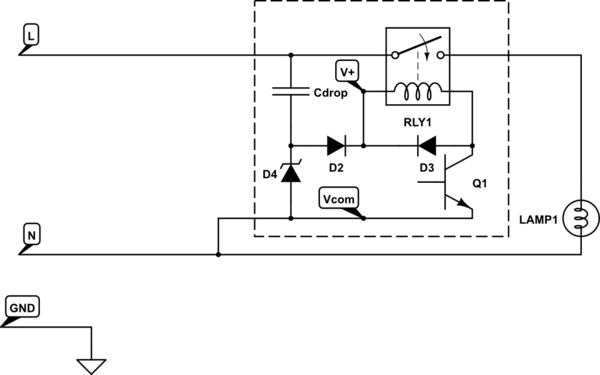
This is a common design. The neutral is there to supply power to the internal circuitry on the board and has nothing directly to do with the output.

There is no need to add a neutral wire since it would simply be connected in and out.

schematic

simulate this circuit – Schematic created using CircuitLab

If not for the electronics, i.e. if you just have a mechanical switch, there is no need for a neutral wire to appear in the junction box at all. That's obviously a problem if that is the case and one is trying to retro-fit a motion detector in place of a mechanical switch.

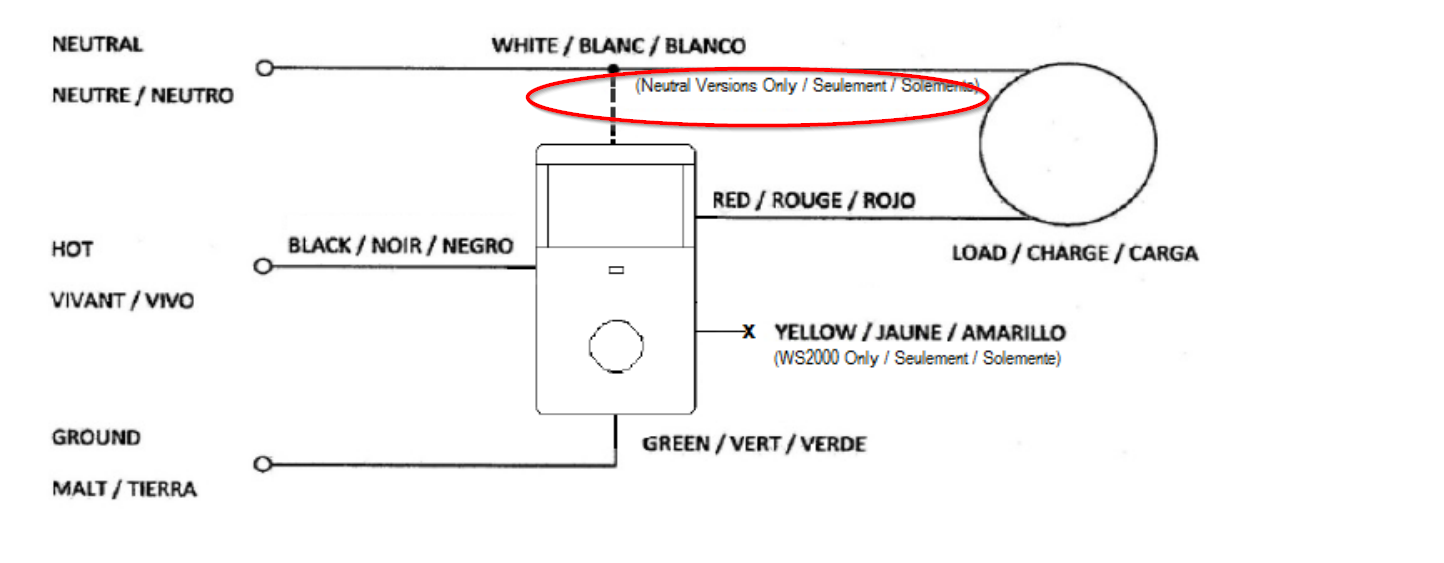
You will find some motion detector circuits advertise that the neutral "is not required". Typically they have the neutral connection but you can leave it open. I don't know offhand whether they draw the small current they need to work through the ground or through the load, but it's one or the other.

Here is an example installation guide drawing from Hubbell. The yellow wire some models have is for so-called '3-way' switching.

enter image description here

\$\endgroup\$
0
\$\begingroup\$

The point is both the lamp and PCB need both Live and Neutral for power in order to work - i.e. the lamp to light up, and the sensor board to detect movement.

Compare the sensor board with a standard light switch first - a standard light switch does not require any power for itself, so it can be on Live wire between mains plug and lamp, while Neutral goes directly from plug to lamp.

If you replace the standard light switch with something that needs power for itself - like an illuminated light switch, or the movemen sensor, you have to provide power for that. Since the Live already comes from mains plug, all you need to do is to add also the Neutral from mains plug to the PCB or illuminated light switch, and then it keeps working.

So in this case, the PCB or illuminated light switch has to control large currents to load through Live wires while only requiring small amount of current to work itself from the Neutral wire.

The difference is where you connect the three neutrals together - the mains plug neutral, lamp neutral, and PCB neutral.

You can split the Neutral from plug into two externally and one Neutral goes to lamp and one Neutral goes to PCB.

Since PCB needs Neutral anyway, you can use the PCB wiring to connect the mains plug Neutral and lamp Neutral together.

So it does not matter where the three Neutrals connect together, externally with a wire nut, or soldered on PCB.

\$\endgroup\$

Not the answer you're looking for? Browse other questions tagged or ask your own question.