3
\$\begingroup\$

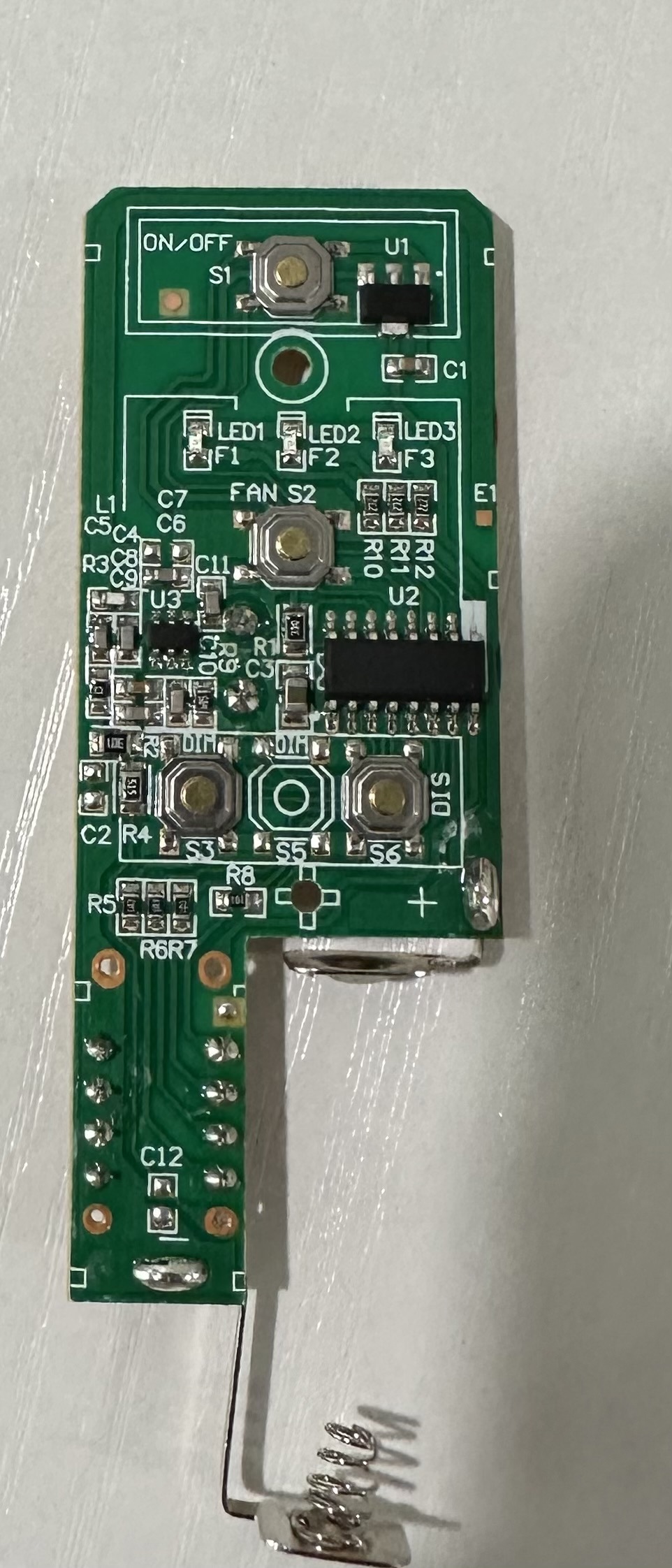
Relatively new to electronics so don’t know all of the terminology, so please excuse me if I express things incorrectly. I have a fan remote that I would like to control using a Raspberry Pi (photo below). The buttons work by completing a circuit when pushed. I have been able to simulate a press by touching the positive and negative sides of the button with a copper wire.

Based on this I had the following idea: solder the collector of a transistor to the positive side of the button, the emitter to the negative side, and the base to a GPIO pin on the Raspberry Pi. This way, output from the GPIO would open the transistor, allowing the electricity to flow from the positive side of the button through the collector, out the emitter into the negative side, effectively bypassing the button and simulating a press.

Would this work? If so, what kind of transistor should I use and do I need a resistor between the GPIO and the base?

If it wouldn't work, why not?

enter image description here

\$\endgroup\$
4
  • 2
    \$\begingroup\$ Do you need to virtually push only one button? Or many of them? Do the buttons share a common wire, or are they multiplexed? Is the common wire ground or supply? So to pull this off, you really need to know how those buttons are used and sensed by the chip. Sometimes buttons are sensed with one pin, but each button uses a different resistance to set different voltages to a single input pin. If that is an infrared remote, it might be easier to just send out the same infrared commands with Arduino, rather than figuring out how to wire them together for simulating push buttons. \$\endgroup\$
    – Justme
    Commented Jun 9 at 13:43
  • \$\begingroup\$ I need to push different buttons but never simultaneously, I was planning one transistor each. It’s a 304 mhz remote, which, I discovered, is a hard frequency to find a transmitter for \$\endgroup\$
    – Antheloth
    Commented Jun 9 at 14:02
  • \$\begingroup\$ probably will not work until you connect the RPi ground to your circuit \$\endgroup\$
    – jsotola
    Commented Jun 10 at 7:33
  • \$\begingroup\$ That’s partly why David answered to use an opto-isolator, I would imagine \$\endgroup\$
    – Antheloth
    Commented Jun 11 at 12:22

1 Answer 1

4
\$\begingroup\$

Would this work?

Maybe. Maybe not. It depends on the circuit to the switch.

The sure-fire wire to do what you want is to use an opto-isolator with a BJT output because it works regardless of how the switches are wired. However, you will have to try the connections across the switch in one direction and then the other direction to see which one works.

The even mode sure-fire way is to use a non-polarized component because it will work regardless of which direction you wire it to the switch. For example:

  • An opto-isolator with a AC/DC output (a solid-state relay with two MOSFETs in series)
  • An opto-isolator with a JFET output (H11F1)
  • A relay, including a reed relay
\$\endgroup\$
3
  • 1
    \$\begingroup\$ Thanks! Will I need a resistor on the GPIO end? \$\endgroup\$
    – Antheloth
    Commented Jun 9 at 15:33
  • \$\begingroup\$ Yes, to limit the LED current. 100 to 470 Ohm usually works. \$\endgroup\$ Commented Jun 9 at 16:18
  • 1
    \$\begingroup\$ Got it working (well, a proof of concept anyway), thank you so much!!! \$\endgroup\$
    – Antheloth
    Commented Jun 21 at 23:00

Your Answer

By clicking “Post Your Answer”, you agree to our terms of service and acknowledge you have read our privacy policy.

Not the answer you're looking for? Browse other questions tagged or ask your own question.