0
\$\begingroup\$

I was inspecting SPI lines on my PCB using an oscilloscope to see if there was a skew between SPI line signals or not. The SPI clock is running at around 4.5 MHz. CPOH= 1 and CPOL = 1.

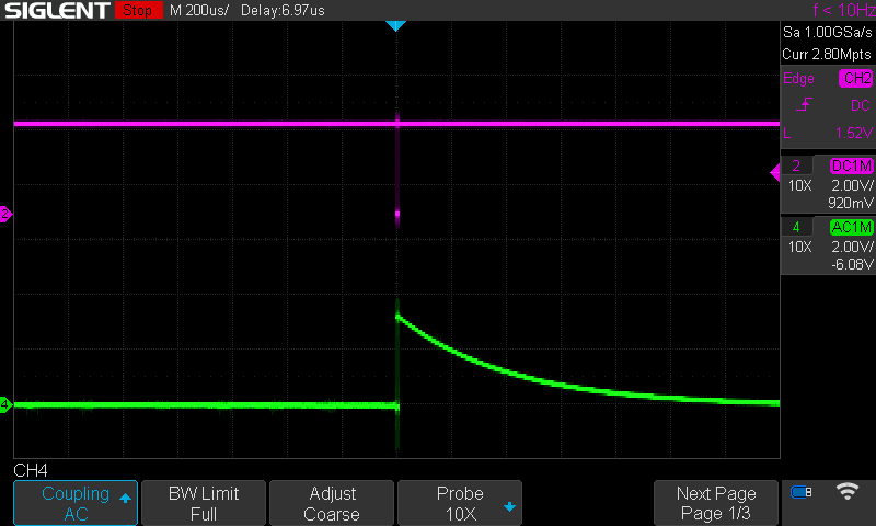
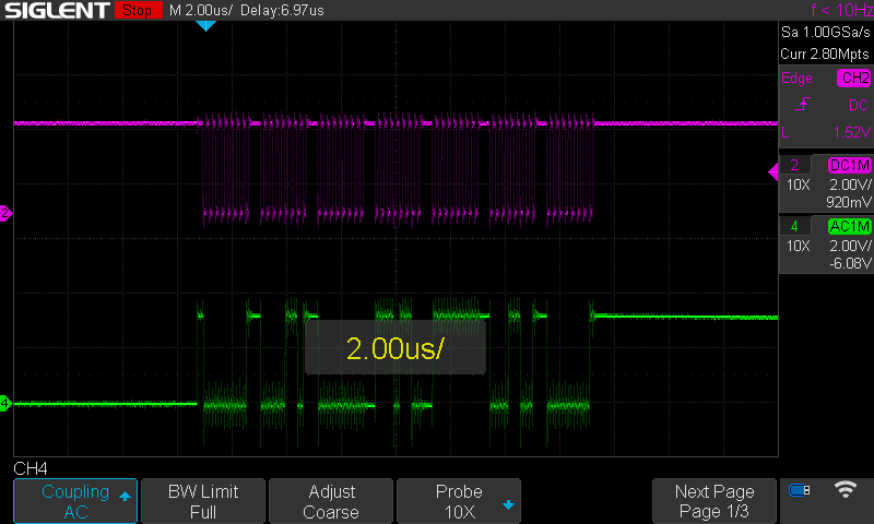
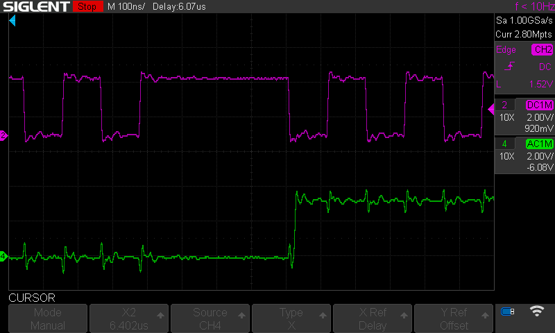
I got the following images (the purple line is the SCLK, while the green line is MISO):

Oscilloscope 200 μs

Oscilloscope 2 μs

Oscilloscope 100 ns

It seems as if the MISO line was discharging a capacitor after the end of the communication. Why is that?

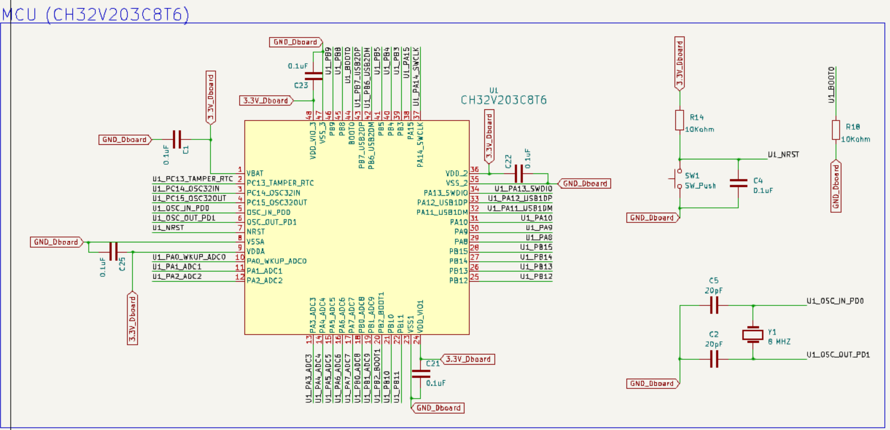
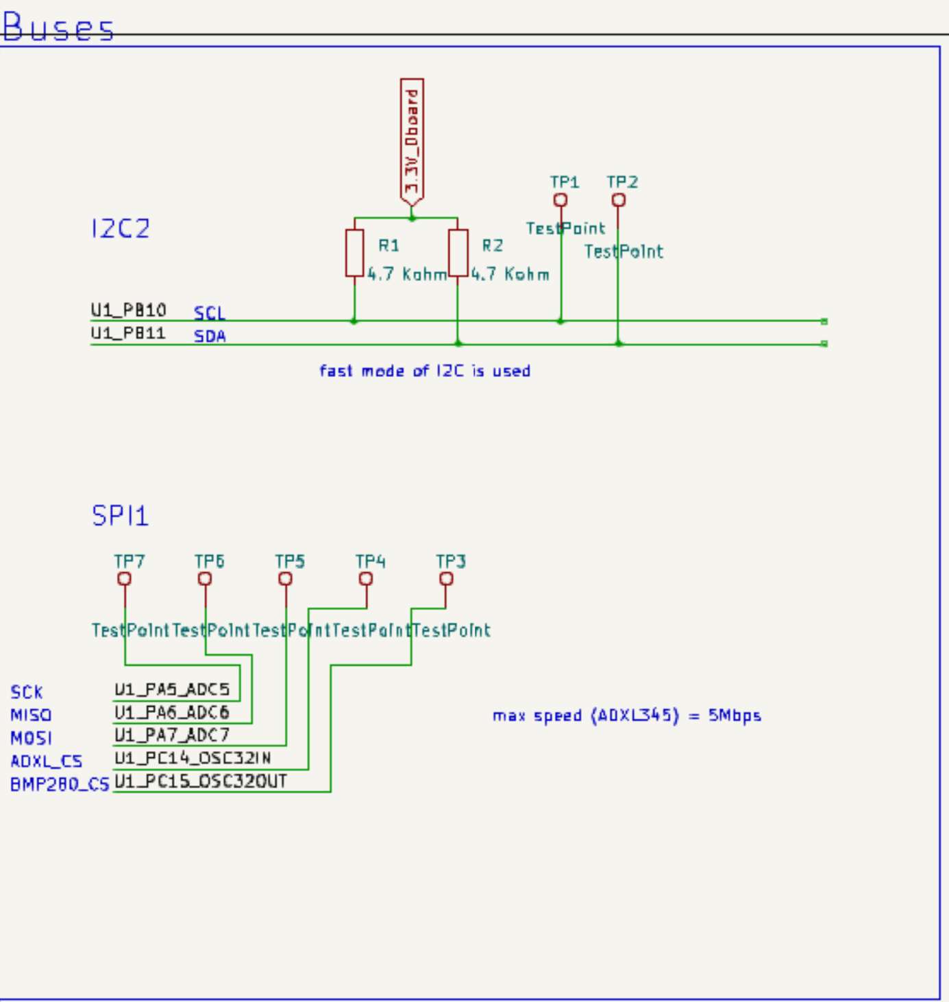
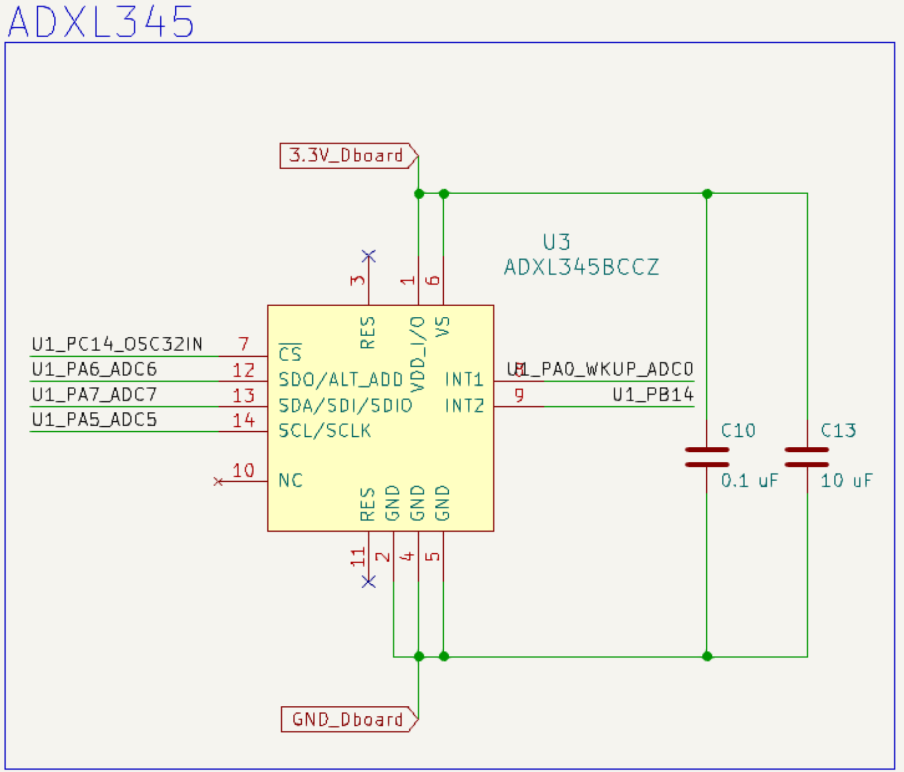
schematic:

enter image description here

enter image description here

enter image description here

\$\endgroup\$
2
  • \$\begingroup\$ Can you please include your schematic \$\endgroup\$
    – Confused
    Commented Jun 12 at 9:48
  • \$\begingroup\$ @Confused, I added the schematics regarding the related IC. \$\endgroup\$
    – abdo Salm
    Commented Jun 12 at 9:53

1 Answer 1

5
\$\begingroup\$

You are correct, it looks like a capacitor discharging, because that is exactly what is happening.

Your scope green channel is set to AC coupled mode. Set it to DC.

If you still see RC discharge waveform, the MISO wiring capacitances are charged to supply voltage, and when MISO goes tri-state, the stray capacitance discharges to 0V through oscilloscope input impedance.

\$\endgroup\$
2
  • \$\begingroup\$ you are right. it was set to AC coupling by mistake, I changed it back to DC coupling but nothing has changed. \$\endgroup\$
    – abdo Salm
    Commented Jun 12 at 9:56
  • 1
    \$\begingroup\$ sorry, now I get it. even if it was set to DC coupling. the MISO line is an open circuit after the end of communication so it will always be discharging parasitic capacitances. \$\endgroup\$
    – abdo Salm
    Commented Jun 12 at 9:58

Your Answer

By clicking “Post Your Answer”, you agree to our terms of service and acknowledge you have read our privacy policy.

Not the answer you're looking for? Browse other questions tagged or ask your own question.