2
\$\begingroup\$

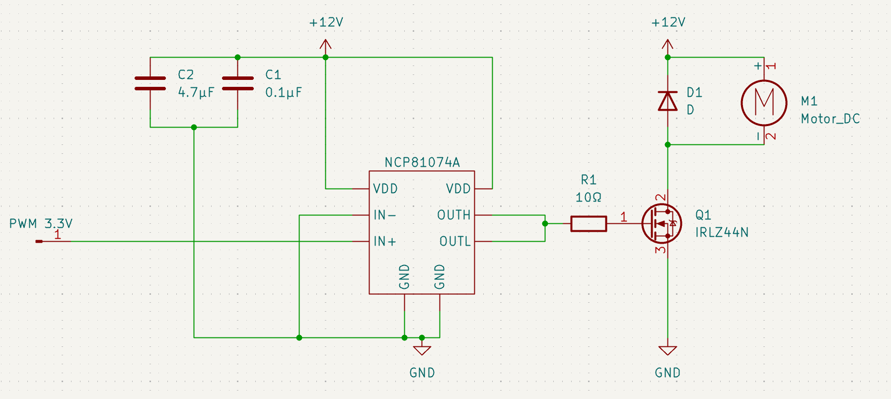
I need to drive a 12 V water pump (max. 2 A) with a PWM signal (20 kHz) from ESP32. I have a few questions about my circuit (I am a beginner).

enter image description here

I have made the following calculations (Learned from YouTube channel MicroType engineering, where he stated, that these are heavily simplified):

Q1 RDSon = 17.5mΩ , junction to ambient thermal resistance = 62 C/W, total gate charge = 63 nC

  1. P = I^2 * R = 2^2 * 17.5 mΩ = 0.07 W --> temperature = ambient 25 C) + 0.07 W * 63 C/W = 29.41 C
  2. I (gate) = 12V/10Ω = 1.2A (this gate driver can source and sink 10A), so OK?
  3. Switching time = 63nC / 1.2 A = 52.5 ns. One cycle = 105 ns --> max frequency = 9.5 MHz (only need 20 kHz)

Questions:

  1. How to determine the value of R1 (this was taken from a YouTube video with this gate driver IC). If I would lower it to 5 Ω, the I (gate) would be 2.4 A, which would still be ok (faster switching speed, less switching losses?)

  2. Wattage of R1? (Ohm's law says that it is 12 V * 1.2 A = 14.4 W. This can't be correct. That is some heavy duty resistor.)

  3. I will be using a different gate driver (these are not available at LCSC.com). Are there any more parameters that I should look into than current sourcing/sinking capabilities (of course that it can handle 12 V)?

  4. Is there something wrong with this schematic, or can I design and order PCB:s and components?

Bonus question:

IRLZ44N seems overkill for this. MDD50N03D has lower RDSon (9 mΩ), lower total gate charge (23.6 nC), and is much cheaper than IRLZ44n. Am I missing something?

Datasheet for MDD50N03D

\$\endgroup\$
2
  • 1
    \$\begingroup\$ The gate is basically a capacitor so it doesn't draw 1.2 A continuously, just a spike of current each time the voltage changes. So you can calculate a much more realistic average current and base the resistor power rating on that. \$\endgroup\$
    – Finbarr
    Commented Jun 13 at 9:14
  • 1
    \$\begingroup\$ Have you used a simulator to check resistor power levels and correct operation. Simulators are free and accurate and give you an insight that is very good. \$\endgroup\$
    – Andy aka
    Commented Jun 13 at 9:14

2 Answers 2

2
\$\begingroup\$

Answers:

  1. I would split R1 to R1H and R1L as I saw in the datasheet of NCP81074 in Figure 2, because production tolerance can lead that shortly both output MOSFETs are on?

  2. 14.4 W for 105 ns per cycle, then ca. 50 us (= 1/20kHz) pause (0 W) -> so ca. 1 : 500 on to off time -> 14.4 W / 500 = ca. 28.8 mW permanent load at R1

  3. propagation? saturation voltages? Probably not a big problem anything here.

  4. your 12V pump has max 2A, so 24 W on its label? Is this 2A max. regular operating current or does the pump have a 6 Ohm internal resistance and it is the motor blocked current of 2 A max.? I ask because a motor with PWM will run more slowly, perhaps even not turn anymore (mechanical minimum resistance), if PWM is too low, then the standing/blocked motor will be just a series resistance plus an inductance. When the inductance is oversaturated or soon in the high pulses, only the resistance is relevant!

Even if you switch on the pump with 100% PWM, it won't turn in the first Milliseconds, therefore the pump starting current can IMHO exceed 2 A... It will accelerate and therefore the current will go down to the nominal operational current (of max. 2A?), within few hundred Milliseconds? <-- so the MOSFET should be able to stand through this startup with (much?) higher current without damage/temporarily overheating (<-- answer to bonus question).

If the power supply is weak (at switching on the pump with e. g. 100%) and its voltage drops, the UGS of Q1 can drop too. Even so low, that its rDSon goes up with the high start current -> it could "burn" the MOSFET. Perhaps make a +11.4V (for the gate driver) from the 12V with a diode, that UGS stays high enough (for some time due to C2 and C1), even when the power supply has a voltage dive.

D1 has to conduct 2A (or even more? Due to start current), best a fast switching diode.

The PWM with 2 A (or more) can generate EMC problems, filter them with right measures, e. g. twist wires to the motor.

There could be parasite capacitances in M1, D1 and the wires around them, that need to be switched too.

These capacitances with the inductance of the motor can lead to high frequency oscillation (EMC). Perhaps a resistor in series to the motor is needed to dampen this oscillation reasonable quickly.

PS: What about a blocked pump and 100% PWM, can the pump overheat (and effectively start to burn)? Therefore a fuse, electronic fuse or thermal switch at the motor or some other overcurrent protection needed?

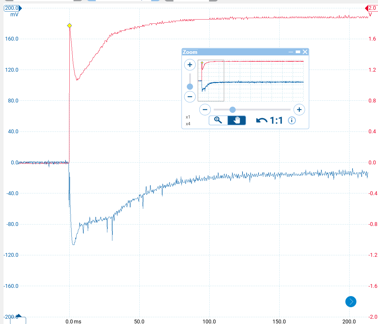
PS2: Here an example of a DC motor (30V 3A nominal) at switching on with relay contacts and powered by a notebook power supply (19V 6A nominal) lowering an height adjustable office table. enter image description here Red is power supply (wrong scale 1Vimg = 10Vreal), blue is current through motor (0.01 Ohm shunt, so -107mVp = +10.7Vp) --> A DC motor consumes factors higher starting current than nominal! Here 10.7A instead of 3A, but even power supply drops to 10.8V, if it stayed at 19V, the current would be ca. 10.7/10.8*19 = 18.8Ap instead 3A nominal.

\$\endgroup\$
3
  • \$\begingroup\$ Thank you. This taught me a lot (still a lot to learn). I tested my pump (2 A in label, so I suspect, that it is reqular operating current) with a cheap PWM motor controller, and it stalls before I can get duty cycle low enough. So back to searching a different pump. Regarding answer 2, I found a formula (for average power) P=f * U^2 * C. This gives 182 mA as average load on R1. Quite a difference. \$\endgroup\$
    – Osk
    Commented Jun 15 at 4:49
  • 1
    \$\begingroup\$ @Osk Are you mixing unit [C] (Coulomb) for charge (with formula letter Q) with unit [F] (Farad) for capacitance (with formula letter C)? Your formula with units in brackets: P[W] = f[Hz] * U[V] ^ 2 * C[F], but C is the capacitance. From formula Q[C] = U[V] * C[F] = I[A] * t[s] --> C[F] = Q[C] / U[V] --> C[F] = 63nC / 12V = 5.25nF and inserted in your formula: P[W] = 20kHz * (12V)^2 * 5.25nF = 15.12 mW Mine with ca. 28.8 mW was ca. 2 times bigger. Was I missing a /2 because during both charging/discharging the voltage is not always peak 12V, but half like in triangles? \$\endgroup\$ Commented Jun 19 at 20:37
  • \$\begingroup\$ Well yes I am mixing units. Thank you for pointing this out. One should really pay attention, when reading posts without deeper understanding of the principles. Just to clarify. The project is a 3D printed hydroponic tower garden where the pump is submerged (well cooled).The intended pump is the same that I have in my boats fresh water tank (usage just on or off). But it is too powerful, and stalls with lower duty cycles. I have found more suitable DC pumps (2-wire brushless), but I have posted a new question regarding driving these. \$\endgroup\$
    – Osk
    Commented Jun 20 at 0:56
0
\$\begingroup\$

A 10A gate driver is massively overkill for something like this. You can find a MOSFET with a gate that can be driven directly from a 3.3V microcontroller output pin. You’re looking for any part with Vgs(on) <= 3.3V and Vds > 12V (with some margin, say 20V) and a reasonably low Rds(on) at that gate voltage (say <0.1ohm).

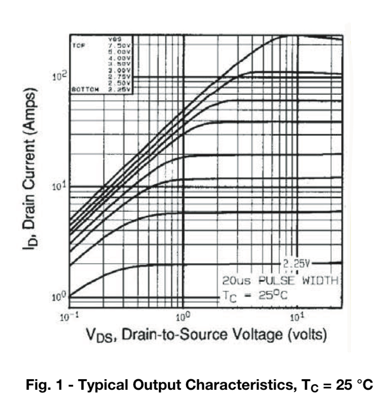
Even your IRLZ44N would probably work driven direct from the microcontroller - the typical curves in the datasheet show it as around Vds<0.1V voltage drop at Vgs=3.3V and Ids=2A, ie Rds<0.05ohm, but that’s not completely guaranteed since it’s just the “typical” characteristics. But it would definitely spin the motor ;)

enter image description here

So why do people use gate driver ICs? Basically, when they need to switch really big MOSFETs (with a really large gate capacitance) really fast. Your selected MOSFET has a total gate charge of 66nC in the datasheet, which is already relatively large; really big ones go to thousands of nC. A microcontroller pin outputting let’s say 10mA would switch it in 66nC/10mA = 6.6 microseconds. You only need to switch twice it every 100 microseconds so that’s okay; but at 100kHz it wouldn’t work. Gate drivers are there to switch MOSFETS like this up to 1000x faster, a high kHz to possibly MHz frequencies. There can be a bit of an efficiency gain from that also because the device spends less time in a high resistance, partly-on state. Again total non-issue here, since everything is relatively low power and the power dissipation during switching would be small.

P.S. It may be good to add some protection diodes so the gate doesn’t go below ground or above the 3.3V supply rail. The microcontroller has those already, but they’re small, and not rated for a lot of repetitive surges. That’s to avoid inductive spikes from the motor from coupling back into the microcontroller. Or, use a hardened 5V microcontroller ;)

P.S. Keep R1, but probably make it 100ohm. It won’t damage the microcontroller to connect a pin directly to a discharged gate capacitance drive it high (it would just current limit internally) but you do want to slow down the edges a bit and limit the max current the gate can kick back into the microcontroller. For the same reason, make D1 a decently high current Shottky diode, and put a snubber (resistor in series with capacitor) parallel to it, and a big capacitor from 12V to ground. Make the connections between all those components as short as possible… Even a small motor’s windings can produce very energetic spikes when switched.

\$\endgroup\$

Your Answer

By clicking “Post Your Answer”, you agree to our terms of service and acknowledge you have read our privacy policy.

Not the answer you're looking for? Browse other questions tagged or ask your own question.