I read application report from Texas Instruments:
Practical Feedback Loop Design Considerations for Flyback Converter Using UCC28740 (SLUAA66)
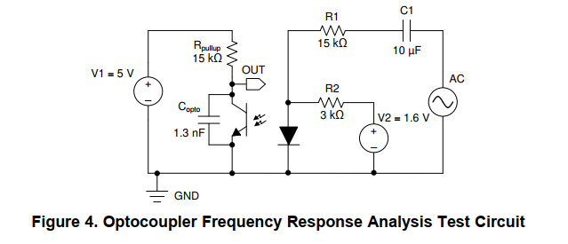
There is a schematic (Figure 4. Optocoupler Frequency Response Analysis Test Circuit) on page 3.
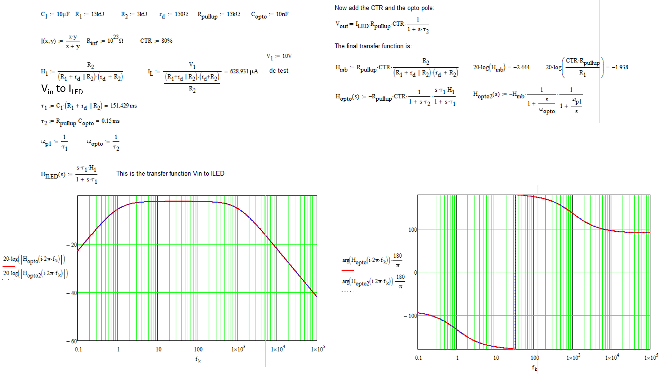
And transfer function is on page 4.
I'm trying to figure out how to get that transfer function.
I know that \$ I_c(s) = CTR * I_d(s) \$ and calculated \$ V_{out}(s) = \frac{R_{pullup}}{(R_{pullup} s C_{opto}+1)} I_c(s) \$
so \$ V_{out}(s) = CTR \frac{R_{pullup}}{(R_{pullup} s C_{opto}+1)} I_d(s) \$
where
\$ I_d(s) \$ - current through diode of optocoupler
\$ I_c(s) \$ - current through transistor/collector of optocoupler
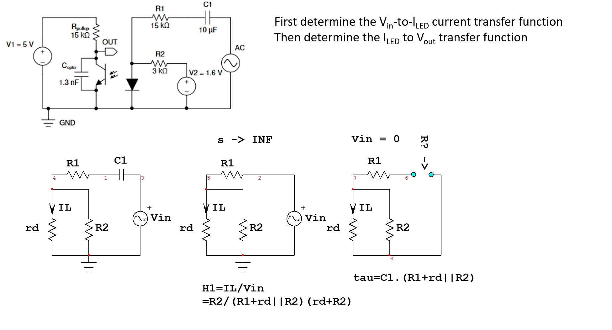
but now I do not know how to continue, how to calculate \$ I_d(s) \$ and so how to get to complete transfer function.
My idea was:
\$ I_1(s) \$ - current through R1 + C1
\$ I_2(s) \$ - current through R2
\$ V_d(s) \$ - voltage of node at the diode anode
V2 is shorted to ground
\$ I_d(s) = I_1(s) - I_2(s) \$
\$ I_1(s) = \frac{V_{in}(s) - V_d(s)}{ R1 + \frac{1}{s C1}} \$
\$ I_2(s) = \frac{V_{d}(s)}{ R2} \$
There is something I am missing. How to continue?


