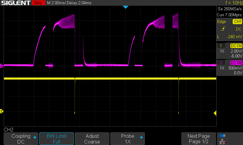
I am using the TPS92692 in buck-boost mode with an analog signal to set Iadj and PWM. When I start the circuit, it consistently goes into fault mode and the fault pin is periodically set low. However, after about 5 seconds, everything works fine and the fault pin is no longer set low but after some time, the current also gradually decreases.
The input voltage is 24 V and the circuit powers 7 LEDs (with a forward voltage range of 2.8-3.4 V for each LED). In this case, Iadj is set to 1.46 V and the PWM is 2.44 V
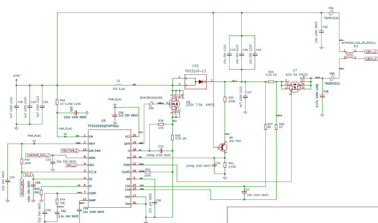
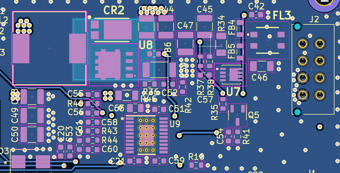
Here is the circuit:
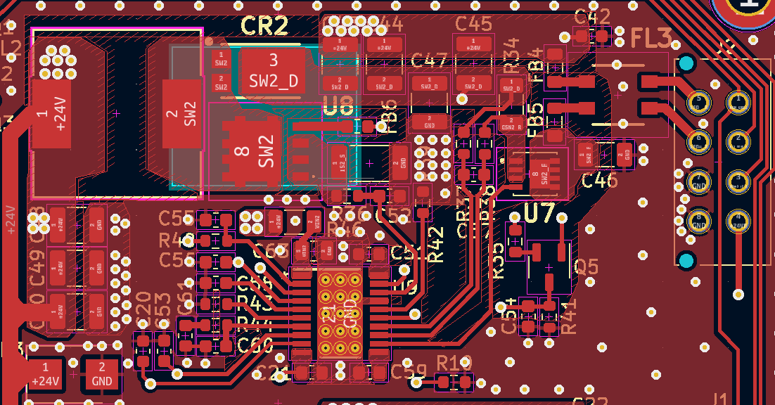
F.Cu :
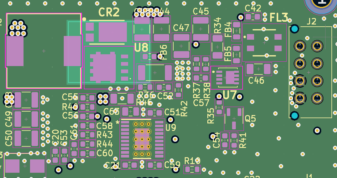
Inner1.Cu :
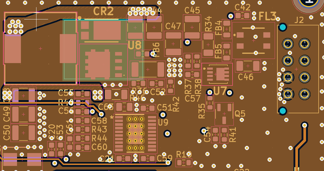
Inner2.Cu :
B.Cu :
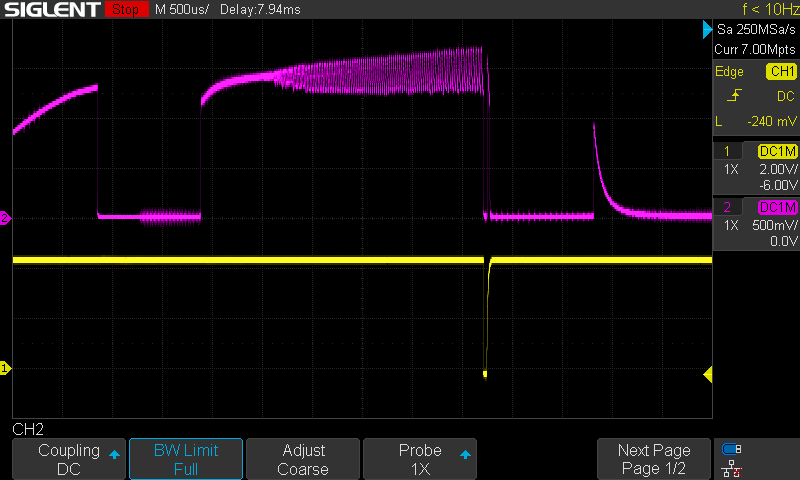
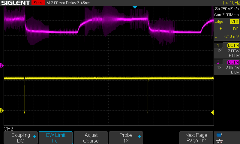
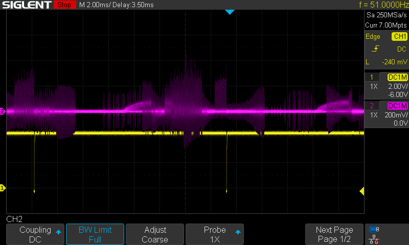
Current start-up signal (yellow) and fault pin signal (purple) :
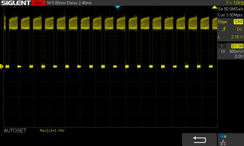
Current after about 5 s:
The datasheet of the IC indicated that there is 4 fault conditions :
• Overvoltage across the LED string (VOV> 1.24 V)
• Under voltage across the LED string (VOV< 100 mV)
• Overcurrent across the LED string (14 × V(CSP-CSN) > 1.5 × VIADJ)
• Cycle-by-cycle switch current limit condition (VIS > 250 mV)
As far as overvoltage and undervoltage are concerned, everything seems to be fine, the voltage is below and above the condition when the pin is on fault:
It is more difficult to say about the cycle-by-cycle switching current limitation condition, because the signal is really noisy:
I also noticed that the RSlope should be 180 kohm instead of 150 kohm. I'll try changing the resistor to see if there's any impact.
Update :
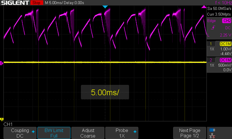
I also measured the output of the comp pin (purple) and noticed that the voltage drop below 1.6 V, which also triggers the fault pin (yellow).
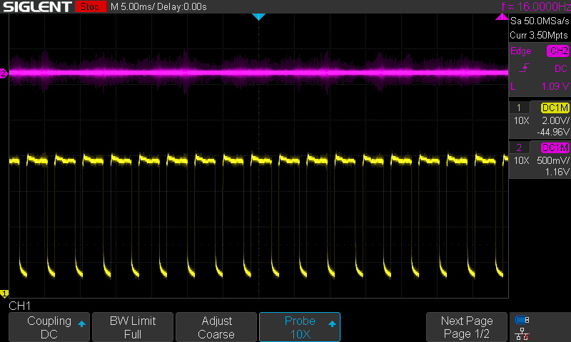
By simply bypassing R44 with a 0.1 uF capacitor, here's what we get (purple is the comp pin and yellow is the voltage on led+):
Here's the calculations I made to compensate for the loop:
\begin{align*} D_{\text{(typ)}} &= 0.475 \\ V_{O(\text{typ\_max})} &= 23.8 \, \text{V} \\ r_{D(\text{typ})} &= 2.31 \, \Omega \\ I_{\text{LED(MIN)}} &= 0.1 \, \text{A} \\ C_{\text{out}} &= 34.7 \times 10^{-6} \, \text{F} \\ L &= 33 \times 10^{-6} \, \text{H} \\ R_{\text{IS}} &= 0.05 \, \Omega \end{align*}
Open Loop Response of Modulator
\begin{equation*} \frac{I_{\text{led}}}{V_{\text{comp}}} = G_0 \frac{1 - \frac{s}{\omega_Z}}{1 - \frac{s}{\omega_p}} \end{equation*}
Small Signal Model Parameter
DC Gain
\begin{align*} G_0 &= \frac{(1-D) V_O}{R_{\text{is}} \left( V_O + D r_D I_{\text{Led}} \right)} \\ G_0 &= \frac{(1-0.475) \times 23.8}{0.05 \left( 34 + (0.475 \times 2.31 \times 0.1) \right)} = 7.3 \end{align*}
Pole Frequency
\begin{align*} \omega_p &= \frac{V_O + D r_D I_{\text{Led}}}{V_O r_D C_{\text{out}}} \\ \omega_p &= \frac{23.8 + (0.475 \times 2.31 \times 0.1)}{23.8 \times 2.31 \times 34.7 \times 10^{-6}} = 12.5 \times 10^3 \end{align*}
Zero Frequency
\begin{align*} \omega_z &= \frac{V_O (1-D)^2}{D L I_{\text{Led}}} \\ \omega_z &= \frac{23.8 (1-0.475)^2}{0.475 \times 33 \times 10^{-6} \times 0.1} = 4.2 \times 10^6 \end{align*}
proportional and integral compensation
\begin{align*} C_{\text{comp}} &= 8.75 \times 10^{-3} \left( \frac{R_{\text{cs}} G_0}{\omega_z} \right) \\ C_{\text{comp}} &= 8.75 \times 10^{-3} \left( \frac{0.16 \times 7.3}{4.2 \times 10^6} \right) = 2.2 \, \text{nF} \end{align*}
\begin{align*} C_{\text{HF}} &= \frac{C_{\text{comp}}}{100} \\ C_{\text{HF}} &= \frac{2.2 \, \text{nF}}{100} = 22 \, \text{pF} \end{align*}
\begin{align*} R_{\text{comp}} &= \frac{1}{\omega_p C_{\text{comp}}} \\ R_{\text{comp}} &= \frac{1}{12.5 \times 10^3 \times 2.2 \times 10^{-9}} = 39 \, \text{k}\Omega \end{align*}
Is the error on Rslope involved? Or an integral compensation is more appropiate?

