0
\$\begingroup\$

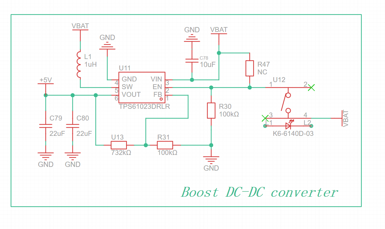
I need some help. I want to power the circuit ON and OFF using a 50mA latching push button. The idea I came up with was to use the En pin of the boost converter. I am using it to turn the boost ON and OFF (En pin when HIGH turns the boost converter ON, EN pin when low shuts it down). I have attached the circuit below would this work?

  • En pin pulled LOW using a weak 100k ohm resistor, therefore to make it OFF in default state.
  • Push switch connected with En and its other end with Vin, to turn it to turn the boost on when pressed.
  • Data sheet link boost converter: https://www.ti.com/lit/ds/symlink/tps61023.pdf

(Don't mind the built-in LED, I would be using the MCU to control it)

enter image description here

\$\endgroup\$
3
  • \$\begingroup\$ R47 "NC" Does that mean you're omitting R47? Why not put that resistor in series with switch and battery? \$\endgroup\$ Commented Jun 30 at 19:36
  • \$\begingroup\$ Yes omitting R47. I just used it in case the push switch method fails, I have soldering points to directly connect the En to HIGH. Do you think controlling the En using the push switch and pull down resistor work? \$\endgroup\$ Commented Jun 30 at 19:48
  • \$\begingroup\$ Yes, but leave R47 at between 100Ω and 1kΩ in series with Vbat and switch, but not pin 2 (EN) \$\endgroup\$ Commented Jun 30 at 22:33

2 Answers 2

0
\$\begingroup\$

A problem with some boost converter circuits, especially those without synchronous rectification, is that the output is connected to the input when the circuit is off. Your part has internal active rectification, and the datasheet states explicitly that the output is fully disconnected when the chip is disabled. SO - your plan should work just fine.

ps. Next time, include a link to the datasheet in your question.

\$\endgroup\$
1
  • \$\begingroup\$ Thank you! and will include the data sheet link. The concept was to use a latching push switch (50mA) to turn the circuit ON and OFF (the load is approx 500mA). \$\endgroup\$ Commented Jun 30 at 19:59
0
\$\begingroup\$

Yes, this is a typical way one might use an enable input. 100 kΩ is a little high for a pull-down resistor, though; I'd use something more on the order of 10 kΩ unless you need to minimize quiescent current (in which case there are better options than a pull-down resistor).

\$\endgroup\$
1
  • \$\begingroup\$ Thanks! I used the 100k ohm to have a weak pull-down resistor so that it can be easily driven HIGH using the push switch (but I think 10k would work as well). The concept is to control the circuit's ON and OFF using a 50mA push switch (latching). The load is greater than 500mA. Any other ways to implement this? If you have any suggestion please \$\endgroup\$ Commented Jun 30 at 19:57

Your Answer

By clicking “Post Your Answer”, you agree to our terms of service and acknowledge you have read our privacy policy.

Not the answer you're looking for? Browse other questions tagged or ask your own question.