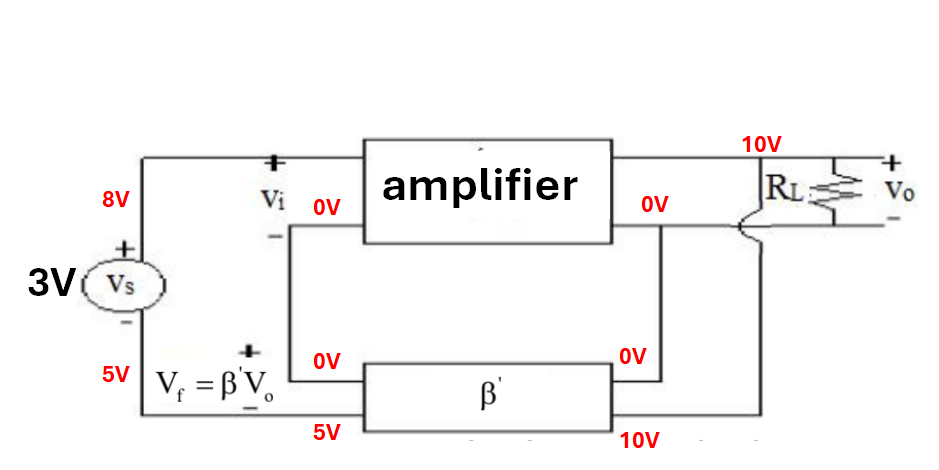
The block diagram below is from my textbook. I don't understand why the input voltage Vi = Vs - Vf. Take an example as the image with numbers on it, I know its not correct in reality but just assume that we are examining in an instance. Let the Vs = 3V, then its amplified resulting in 10V at the output, the feedback block then takes half of it (5V) and feed it back to the input. The problem is, according to the flow (as I think is true) the input voltage is now the sum of source voltage and feedback voltage (5+3=8V). And it obviously does not reflect the given formula which is Vi = Vs - Vf. I think the problem arise when they sample the voltage that way (upper line to the source and bottom line to the base). This is a part of my basic electronics class and I do not major in electrical engineering so my background could be insufficient for this; however, any answer will be appreciated.
-
\$\begingroup\$ In the first figure, you can see that Vin = Vs - Vf simply by KVL for that loop. In the second figure, that formula is also true but you forgot the sign of the fedback voltage. Vin = Vs - Vf = 3V - (-5V) = 3V + 5V = 8V. \$\endgroup\$– internetCommented Jul 6 at 7:06
-
\$\begingroup\$ Taking your numbers, the amplifiers open loop gain Ao=10V/3V=+3.333 is positive. With beta=0.5 the feedback voltage is Vf=+5V. With Vi=Vs-Vf=3-5=-2 volts the output goes from +10 volts to (-2*3.333)=-6.66 volts.....and so on (alternating plus/minus). Finally, the output approaches a steady-state at a closed-loop gain Acl=Ao/(1+0.5Ao)=0.435. \$\endgroup\$– LvWCommented Jul 6 at 9:46
-
\$\begingroup\$ @LvW I know the correct formula, however, when I try to follow the node voltage along the diagram, it appears to sum up with the source voltage. \$\endgroup\$– Thành NguyễnCommented Jul 6 at 9:57
-
\$\begingroup\$ @ThanN. So - did I make any error? Please note that my above calculation starts at the very first moment (after switch-on) when no feedback signal is available. That was my assumption for the open-loop gain Ao. Some moments later, when negative feedback comes into play, the situation changes and the output goes from + to minus...and so on... until the final state has arrived. Such a timely sequency is not very realistic but it can explain why and how tzhe circuit arrives at an equilibrium. \$\endgroup\$– LvWCommented Jul 6 at 10:21
-
\$\begingroup\$ @LvW I understand how it would stabilize the output voltage BUT I'm confused at the point where the feedback voltage is mixed with the source voltage. Due to the bottom figure, if you were to calculate the voltage difference between 2 terminal, which is Vi, it would be 8V, not -2V. I know that the voltages actually subtract; however, as I try to follow the path, it appears to me that Vi = Vs + Vf. (I don't say that my diagram is correct, I just want to know how did I get it wrong). \$\endgroup\$– Thành NguyễnCommented Jul 6 at 10:44
1 Answer
Why input signal of negative feedback amplifier is Vs - Vf?
The indicated voltage polarities must be obeyed when applying KVL to the input circuit.
Starting with \$V_{s-}\$, then proceeding clockwise around the input circuit, the voltage increases across \$V_{s}\$, so treat it as positive for KVL purposes. Then the voltage decreases across the other two voltages, so treat them as negative for KVL purposes. $$ V_{s}-V_{i}-V_{f}=0 $$ $$ V_{i}=V_{s}-V_{f} $$
The original diagram has no ground reference, so care must be taken when applying voltages to the nodes as they require a reference. In the voltage labeled diagram, there are two 0V indicators so to avoid confusion, the input circuit uses the 0V label on the input as the reference for the input circuit only.
The voltages in the blue circle are incorrect. 5V should be -5V according to the polarity indicators on the output and feedback voltages and the defined 0V reference. Using the corrected voltages and assuming steady state, then the open loop gain of the amplifier is \$A_{OL}=-5\$.
So now all the title question can be verified.


