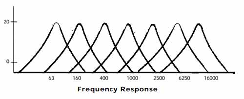
I have built the following circuit based on a proven MSGEQ7 based circuit design, which comes from the datasheet and elsewhere on the internet. I have built and coded to this circuit previously, with a 5V power supply, no problem.

The audio input is a sparkfun electret microphone breakout board with onboard op-amp-based amplification circuit. This too, I have successfully used on a previous project hooked up to the MSGEQ7. It worked fine there, but at that time I used an Arduino 3.3v pin to power this (here both the MIC BoB and the MSGEQ7 are on 3.3V rails).
The only difference between this circuit and the last one I built (that I can tell anyway) is the fact that I'm now running both MSGEQ7 and the BOB off a 3.3V rail.
The circuit "kinda" works, but the analog readings do not seem calibrated properly.
Here is a sample of the the output I'm getting:
RAW EQ      392 406 630 803 842 973 886
RAW EQ      341 818 936 1022    1022    1022    1021
RAW EQ      590 812 950 860 1023    1023    1021
RAW EQ      550 894 1022    1022    1023    1022    1020
RAW EQ      561 926 953 1023    1023    1022    1006
RAW EQ      565 805 918 966 1022    1023    1013
RAW EQ      525 835 1013    999 1023    1023    1022
RAW EQ      611 862 884 1015    1022    1023    1012
RAW EQ      541 794 802 849 1023    1023    1012
RAW EQ      449 759 993 928 1023    1022    1002
RAW EQ      400 858 1006    1013    1023    1022    1015
RAW EQ      460 876 934 1023    1022    1023    1013
RAW EQ      617 845 869 976 1023    1022    1022
RAW EQ      729 814 981 1023    1023    1022    1015
As you can see the last 3/4 bands are all pretty much maxing out!
Here is the relevant Arduino code:
Init Routine
//initialise MSGEQ7 chip
void initMSGEQ7(int analog, int strobe, int reset)
{
#if defined DEBUG
    Serial.println("MSGEQ init");

    Serial.print("Analog Pin");
    Serial.println(analog);

    Serial.print("Strobbe Pin");
    Serial.println(strobe);

    Serial.print("Reset Pin");
    Serial.println(reset);

#endif
//set up MSGEQ7 pins
pinMode(analog, INPUT);
pinMode(strobe, OUTPUT);
pinMode(reset, OUTPUT);
analogReference(DEFAULT);

//turn off comms to MSGEQ7 to start with
digitalWrite(reset, LOW);
digitalWrite(strobe, HIGH);
//prep the MSGEQ7 to read in the frequency bands
digitalWrite(reset, HIGH);
digitalWrite(reset, LOW);
}
Reading code
//read the EQ
void readEQ(int strobe, int analog, int (&bands)[7])
{
#if defined DEBUG
    Serial.print("RAW EQ\t\t");
#endif

//read in the bands
for (int i = 0; i < 7; i++)
{
    digitalWrite(strobe, LOW);
    bands[i] = analogRead(analog);
    delay(5);
    #if defined DEBUG
        Serial.print(bands[i]);
        Serial.print("\t");
    #endif
    digitalWrite(strobe, HIGH);
}
#if defined DEBUG
    Serial.println();
#endif
}
The question: How do I make this give me readings in a better spread from 0 to 1023 via the Arduino's analog inputs.
I have rebuilt the circuit a number of times, using completely new components (passives, IC, cable and the BoB), the results are the same.
I also have an unregulated 3.7V rail (from a LIPO battery) which I could use -- the 3.3V regulated supply comes from an Arduino Pro Mini 8MHz 3.3V edition which takes in the unregulated 3.7V LIPO power supply.


 (
(