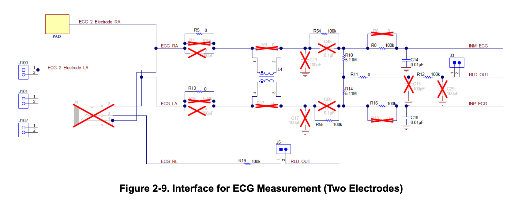
I'm designing a PCB for single lead ECG measurement and I ran across this TI reference design that contains a common-mode choke (P/N Murata DLW31SN900SQ2L). What's strange is that I can't find any other similar circuit designs that contains a choke. I understand the principle, and I can certainly find many power or signal (like ethernet) circuits with them (even on ECG boards, but using the choke to filter any DC-DC conversion noise). I'm curious if anyone has any opinions on the design theoretically, as I haven't decided yet if I'll include space in the test PCB.
1 Answer
Remember the reference design includes a 2.4 GHz Bluetooth transceiver, literally on the same PCB. I believe the common-mode choke is there to reduce potential RF interference on the ECG electrode inputs. Admittedly the BLE transmitter operates at only a few milliwatts of power, but the ECG signal is also of low amplitude, in the millivolt range, and the input impedance of the ECG amplifier is high. If you can afford the space, include the choke.
The BLE transmitter isn't the only potential source of interference. Signals from a strong broadcast transmitter in the area could also interfere or overload the ECG inputs. The ECG leads and the human body itself can be a pretty good antenna for these signals.
-
\$\begingroup\$ The BLE transmitter is a good point. I was thinking more in terms for the frequency range of interest (the ECG "standard" is < 150 Hz), of which I was most concerned about 50/60 Hz line noise. Although, that's probably better solved with a low-pass filter (the IC I'm considering already includes a digital one, but I guess an analog one wouldn't hurt, and could cut down on any aliased noise). \$\endgroup\$ Commented Jul 9 at 19:50
-
\$\begingroup\$ Yes, in general you cannot rely on digital filters for EMI filtering. Nor ASIC inputs where the internal clamp diodes limit signal range to the supplies. It has to be done with components that are free of aliasing, and remain linear (or at least well-behaved) up to whatever impulse might be encountered (usually ESD is the most extreme case). \$\endgroup\$ Commented Jul 9 at 20:29
-
\$\begingroup\$ Adam, if you use the right leg drive as shown on your schematic, line frequency interference will likely not be a problem. \$\endgroup\$ Commented Jul 10 at 3:20

