3
\$\begingroup\$

From Razavi's Fundamentals of Microelectronics book: enter image description here
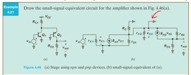
I don't understand where did this ground come from? The resistor r_pi2 is connected between the emitter and base and then the base is grounded (but not the emitter). Here, the emitter is also grounded, why?

\$\endgroup\$
2
  • 2
    \$\begingroup\$ That ground connection is wrong, the emitter of the second bjt is connected to the collector of the first one. \$\endgroup\$ Commented Jul 11 at 6:46
  • 1
    \$\begingroup\$ Always refer to the errata posted by the authors. No book is perfect. In support of Rohat's response, here is the link for the errata. It is stated that the GND connection at the emitter of Q2 must be omitted. seas.ucla.edu/brweb/teaching/… \$\endgroup\$
    – a360pilot
    Commented Jul 11 at 7:57

1 Answer 1

3
\$\begingroup\$

There's a mistake there.

Quite possibly the authors meant to indicate the grounded base of Q2 but misdrew the ground connection.

As you might remember from the BJT small signal AC model, the resistance \$r_{\pi}\$ appears across the base and the emitter. The collector of Q1 connects to Q2's emitter, also the Q2's base is grounded so the \$r_{\pi2}\$ becomes in parallel with \$r_{O1}\$ and \$r_C\$.

\$\endgroup\$

Your Answer

By clicking “Post Your Answer”, you agree to our terms of service and acknowledge you have read our privacy policy.

Not the answer you're looking for? Browse other questions tagged or ask your own question.