0
\$\begingroup\$

I'm new to this forum and hope you can help me. I am in the process of designing an input filter for a DC-DC step-down converter 12V-5V/1A (Pic.1). enter image description here
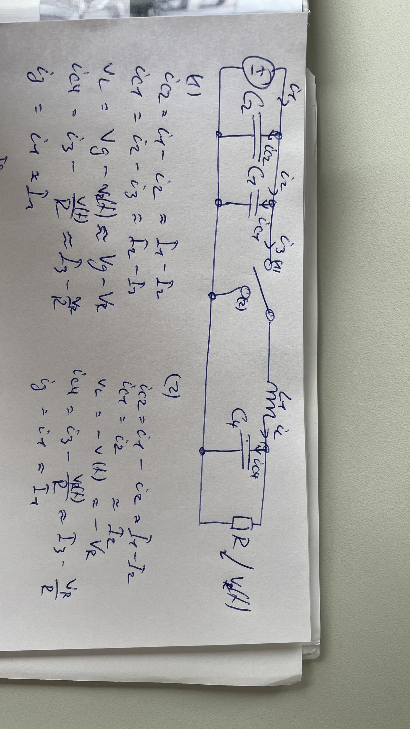
I am trying to determine the transfer function and input impedance of the converter using the methods from the book Fundamentals of Power Electronics by Robert W. Erickson, Dragan Maksimović. In my case, I am looking at a buck converter with 2 input capacitors. From this circuit, I would like to obtain the AC small-signal circuit and also the canonical form.

Can anyone verify if the AC small signal circuit is correct (Pic 2)? And does anyone know how to get the canonical from it, or what steps are necessary to transfer the capacitors to the secondary side (Pic.2)?

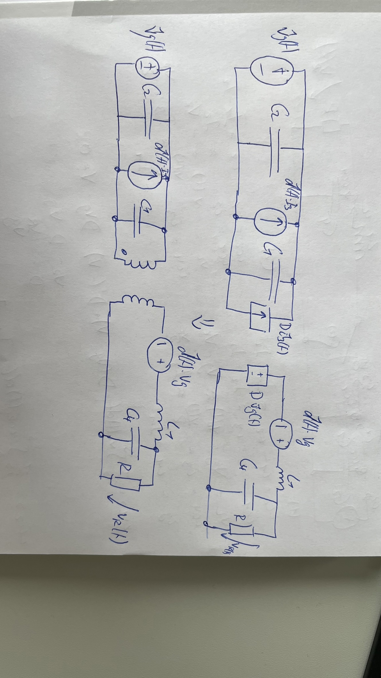
enter image description here

\$\endgroup\$
6
  • \$\begingroup\$ You can get rid of the two input capacitors, they are useless for the analysis as the voltage source is perfect. They would have a role if a) the voltage source is affected by an output resistance (or impedance) and b) if they add an equivalent series resistance or ESR. If you want the control-to-output transfer function, you consider \$v_{in}\$ equal to 0 V in ac. I recommend you have a look at my APEC 2013 seminar, it covers small-signal analysis using the PWM switch from Vatché Vorpérian published in 1986. \$\endgroup\$ Commented Jul 16 at 18:49
  • \$\begingroup\$ So do the two input capacitors have no influence on the input impedance of the buck converter? \$\endgroup\$ Commented Jul 18 at 5:05
  • \$\begingroup\$ Oh, sure, if this is \$Z_{in}\$ that you want, they surely do but for this exercise, they are usually not accounted for. Check my APEC 2017 seminar, I derived the input impedance in open- and closed-loop conditions. \$\endgroup\$ Commented Jul 18 at 5:36
  • \$\begingroup\$ @VerbalKint To understand this correctly from your seminar. Make it simple and pull the 2 input capacitors from the buck converter to the filter side so that they are taken into account in the output impedance of the filter. Correct? \$\endgroup\$ Commented Jul 18 at 8:00
  • \$\begingroup\$ Yes, this is how it has to be done: the input caps are part of the EMI filter while the buck \$Z_{in}\$ is determined without them. Then you can then compare \$Z_{out}\$ of the filter and \$Z_{in}\$ of the buck (or another dc-dc converter). \$\endgroup\$ Commented Jul 18 at 8:11

0

Your Answer

By clicking “Post Your Answer”, you agree to our terms of service and acknowledge you have read our privacy policy.