I am struggling with the simplest program. I am working with PIC microcontroller and am trying to get the LED to blink with MCC configure in MPLAB. There aren't many steps involved in this yet I can't figure out why my LED is not flashing. The steps, according to this video MCC melody Timer0 PLIB driver: 100ms Timer - Youtube are:
1)Open up MCC melody
2)select Timer0 from Device resources>drivers>Timer panel and add it
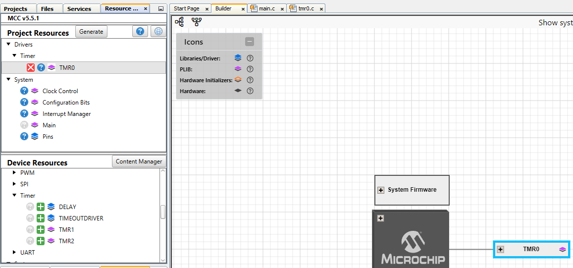
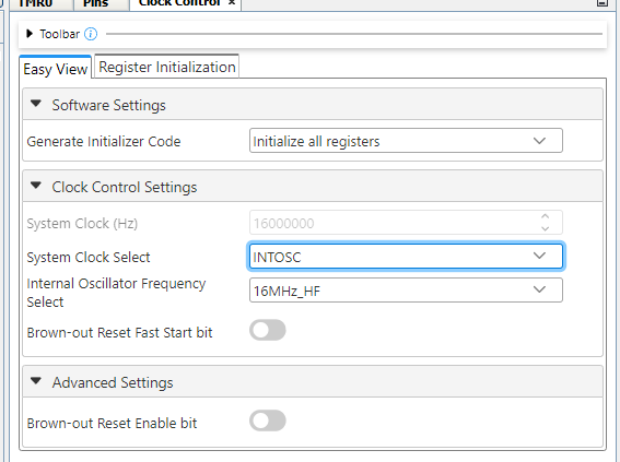
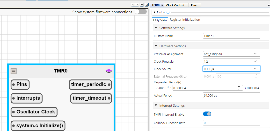
3)select Fosc/4 (internal oscillator) and enable interrupt
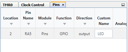
4)configure a pin for output blinking
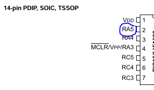
5)Hit "Generate Code" and then create a pointer to Timer0 struct and pass Timer_call_back_10us (this is the time that falls into the range set by Timer0 in MCC melody from step 3) into argument of TimeoutCallbackRegister. toggle LED pin RA5.
6)enable global interrupt
#include "mcc_generated_files/system/system.h"
const struct TMR_INTERFACE *Timer= &Timer0;
/*
Main application
*/
void Timer_Callback_10us(void){
LED_Toggle();
 }
 int main(void)
 {
 SYSTEM_Initialize();
 Timer->TimeoutCallbackRegister(Timer_Callback_10us);
 // If using interrupts in PIC18 High/Low Priority Mode you need to
 enable the Global High and Low Interrupts
 // If using interrupts in PIC Mid-Range Compatibility Mode you need to
 enable the Global and Peripheral Interrupts
 // Use the following macros to:

 // Enable the Global Interrupts
 INTERRUPT_GlobalInterruptEnable();

 // Disable the Global Interrupts
 //INTERRUPT_GlobalInterruptDisable();

 // Enable the Peripheral Interrupts
 INTERRUPT_PeripheralInterruptEnable();

 // Disable the Peripheral Interrupts
 //INTERRUPT_PeripheralInterruptDisable();


 while(1)
 {
 }
 }
The code for the timer struct callback register comes from the timer0.c created after generating the MCC melody code. Here it is:
#include <xc.h>
#include "../tmr0.h"

volatile uint8_t timer0ReloadVal;

const struct TMR_INTERFACE Timer0 = {
.Initialize = Timer0_Initialize,
.Start = NULL,
.Stop = NULL,
.PeriodCountSet = Timer0_PeriodCountSet,
.TimeoutCallbackRegister = Timer0_OverflowCallbackRegister,
.Tasks = NULL
};

static void (*Timer0_OverflowCallback)(void);
static void Timer0_DefaultOverflowCallback(void);

void Timer0_Initialize(void)
{
// PS 1:2; PSA not_assigned; TMRSE Increment_hi_lo; TMRCS FOSC/4; mask
the nWPUEN and INTEDG bits
OPTION_REG = (uint8_t)((OPTION_REG & 0xC0) | (0xD8 & 0x3F));

// TMR 0;
TMR0 = 0x0;

// Load the TMR value to reload variable
timer0ReloadVal = 0;

//Set default callback for TMR0 overflow interrupt
Timer0_OverflowCallbackRegister(Timer0_DefaultOverflowCallback);

//Clear Interrupt flag before enabling the interrupt
INTCONbits.TMR0IF = 0;

//Enable TMR0 interrupt.
INTCONbits.TMR0IE = 1;

}

uint8_t Timer0_Read(void)
{
uint8_t readVal;

readVal = TMR0;

return readVal;
}

void Timer0_Write(size_t timerVal)
{
// Write to the Timer0 register
TMR0 = (uint8_t) timerVal;
}

void Timer0_Reload(void)
{
// Write to the Timer0 register
TMR0 = timer0ReloadVal;
}

void Timer0_PeriodCountSet(size_t periodVal)
{
timer0ReloadVal = (uint8_t) periodVal;
}

void Timer0_OverflowISR(void)
{

//Clear the TMR0 interrupt flag
INTCONbits.TMR0IF = 0;

TMR0 = timer0ReloadVal;
if(Timer0_OverflowCallback)
{
  Timer0_OverflowCallback();
}
}

void Timer0_OverflowCallbackRegister(void (* CallbackHandler)(void))
{
Timer0_OverflowCallback = CallbackHandler;
}

static void Timer0_DefaultOverflowCallback(void)
{
//Add your interrupt code here or
//Use Timer0_OverflowCallbackRegister function to use Custom ISR
}
7)I downloaded the program to the PIC
8)I got the following error
The configuration is set for the target board to supply its own power
but no voltage has been detected on VDD. Please ensure you have your
target powered up and try again.
Connection Failed.
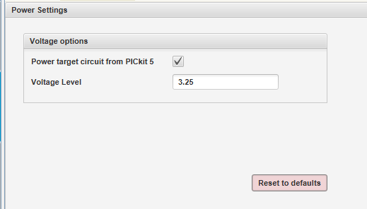
To get around this error. I simply opened MPLAB IPE
I clicked power settings and made sure the PICkit5 votlage was set
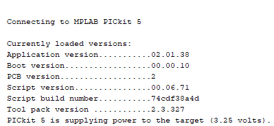
then I clicked connect
The following message (sorry. there wasn't an error here) showed up
edit: i changed the prescalar to 1:256 (16ms) and the LED is still not blinking

