0
\$\begingroup\$

enter image description here

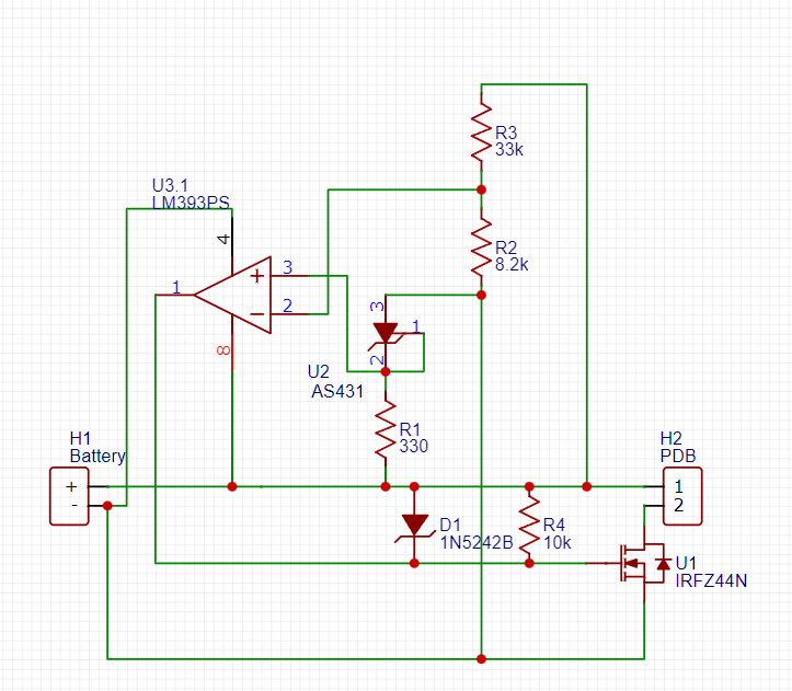
This is the current circuit design that I have, some notes, the majority of these components are chosen simply because they are what I have, namely the AS431 instead of TL431, irfz44n as the switching fet and LM393 comparator. I have included the 1N5242 zener to prevent Vgs from exceeding its max value

My question is as follows, I am worried that with this design, the circuit will oscillate. The load for this circuit will be somewhere between 60 and 70 watts, what I am concerned about is that under load, Vbat will drop lower and eventually reach the ~12.6V threshold set by the voltage divider, then once the mosfet switches off, it will rise above the threshold voltage again and oscillate until the battery drains low enough to always be below 12.6. Will this be a significant problem? The circuit will have to power some sensitive electronics, a Rpi, esp32 and some sensors so large oscillations on the power lines would be really problematic. If this will cause issues, is there any easy solution to prevent such oscillations or should I switch to an entirely different overdischarge protection topology?

P.s I am pretty sure I put the + and - on the comparator the wrong way around, correct me if i'm wrong...

\$\endgroup\$

1 Answer 1

0
\$\begingroup\$

I see a few problems:

  1. Biasing resistor of the 431. When the battery is charged enough i.e. have higher than 12.5 VDC, 330R brings a biasing current of more than 30 mA which is way too high already. Normally, 1 mA is more than enough. Also it'll discharge the battery, let alone the power dissipation.
  2. R4 is the pull-up of the comparator output, and applies positive rail voltage to the MOSFET's gate by default but it's already shorted by the forward-biased diode, D1, so the R4 loses its "pull-up resistor" job.
  3. Related to "2" above, if the comparator outputs 0V there's going to be a significant current flow through D1 as it'll short the battery rails (anode at +, cathode at – through comparator).
  4. Look at the comparator arrangement again. If the battery voltage is higher than the threshold voltage which equals to \$\mathrm{V_{bat} = (33/8.2+1)\cdot 2.495 = 12.5V}\$, the comparator will output 0V i.e. pull the OUTPUT pin low and short to the negative rail. Now related to "3", the MOSFET will be off when the battery is charged enough, and since the output will be 0V (approx) the D1 may die due to overcurrent and fail-short which may possibly result in destruction of the battery.

So your circuit will not work as an over-discharge protection. It will overdischarge (or maybe even destroy) the battery. Even if you make the arrangement correctly, the unnecessary discharge due to biasing is still there. Also, if you do have to use these components then consider hysteresis with the comparator.

Finally, I'd recommend circuits and ICs specialised for this purpose, such as DW-01.

\$\endgroup\$
2
  • \$\begingroup\$ So if i improve this current design by: Swapping the connections on the + and - terminals of the LM393 so that the mosfet is on when the voltage divider's output is > 2.495V changing the config of the zener diode so that the 10k resistor is in series with it to still limit Vgs without shorting the lm393's output when it's pulled low adjusting R1 to be 10k to give 1mA at the battery threshold voltage ~12.6 and slightly more at typical battery voltages will this then work or would i have to deal with the oscillation problem? \$\endgroup\$ Commented Jul 22 at 12:38
  • \$\begingroup\$ @CharlieHeadon Swapping the connections on the + and - terminals of the LM393 yes. changing the config of the zener diode so that the 10k resistor is in series with it Placing the Zener across the GS of the MOSFET (cathode at G) is enough. adjusting R1 to be 10k to give 1mA at the battery threshold voltage ~12.6 and slightly more at typical battery voltages yes would i have to deal with the oscillation problem? Making the mentioned changes on their own will not prevent the comparator from oscillating. Consider "hysteresis" for the comparator as well, as I stated in my answer. \$\endgroup\$ Commented Jul 22 at 12:42

Your Answer

By clicking “Post Your Answer”, you agree to our terms of service and acknowledge you have read our privacy policy.

Not the answer you're looking for? Browse other questions tagged or ask your own question.