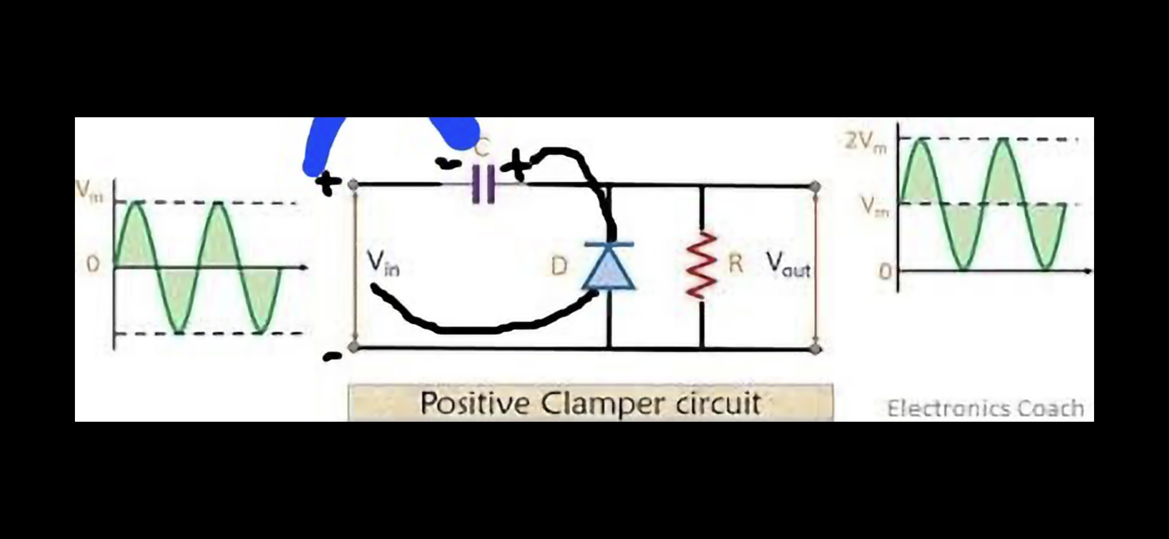
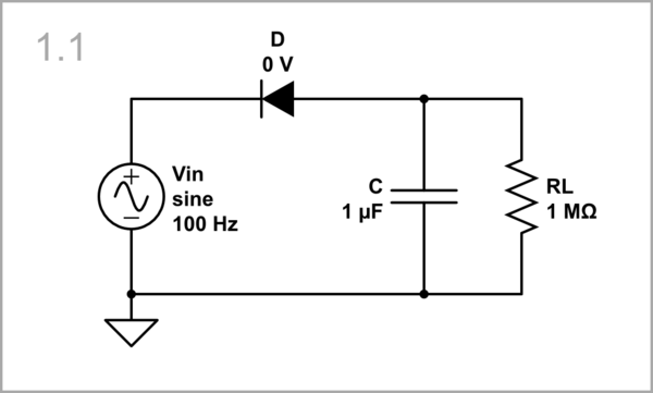
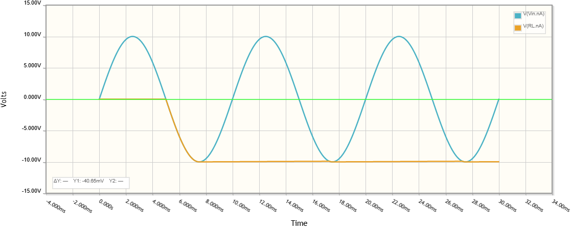
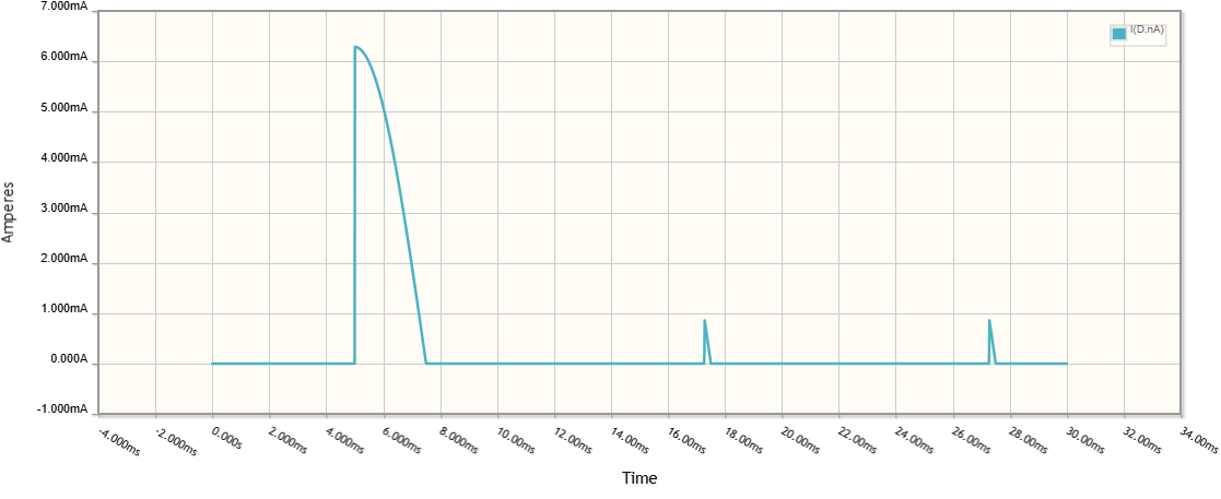
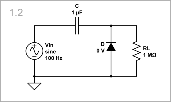
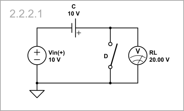
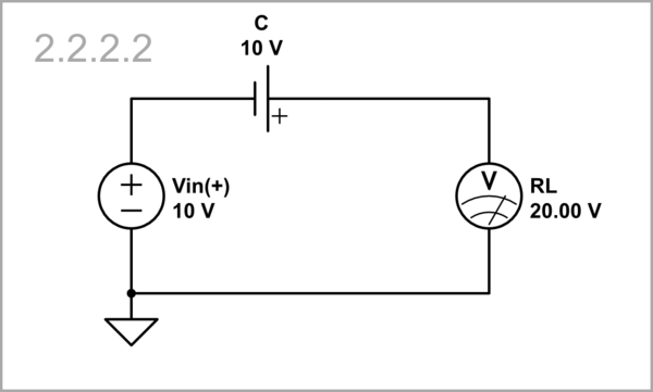
Despite this circuit having only two (or three, if you include the resistor) elements, it is hard explain without sticking strictly to the algebra and KVL, and separating the roles of current and voltage. After you "see it" the first time, it seems obvious, but I can't seem to find an analogy to describe it. Perhaps there's none, and that's why the internet doesn't have any decent "explain like I'm 5" type treatments.
This circuit performs what is known as "DC restoration", a name which will make more sense towards the end. I'll try to keep it intuitive, but you'll need to closely follow the algebra.
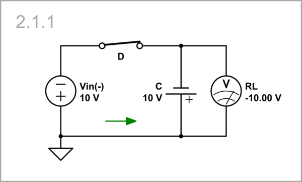
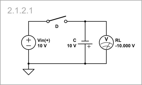
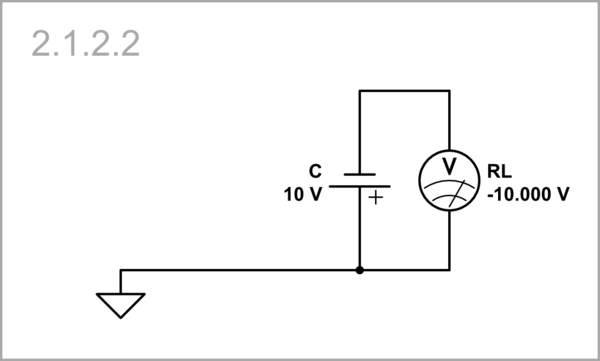
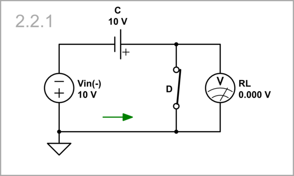
Forgetting the resistor for the moment, and assuming that the capacitor is initially discharged, figure out what will happen in the following two scenarios:
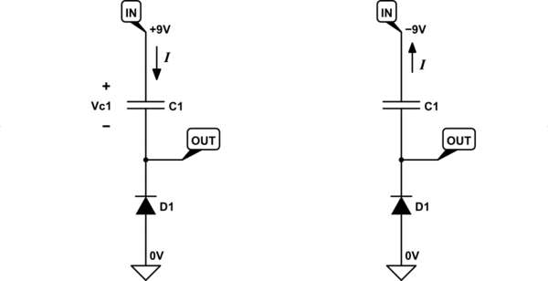
simulate this circuit – Schematic created using CircuitLab
The ±9V input signal is just some arbitrary amplitude I've chosen for illustration. It could be any amplitude.
On the left, where the top node IN is held at potential \$V_{IN}=+9V\$, which represents the positive half of the input cycle. Current must flow from the higher potential to lower, and since 0V (which is lower) is at the bottom, current direction wwould be downwards. I say "would be" because that's not permitted by the diode, and in this state, current is \$I=0\$.
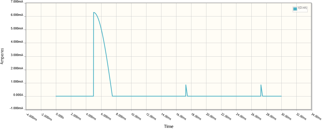
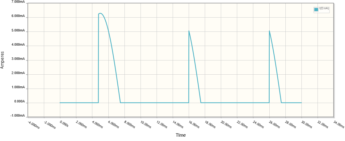
On the right, \$V_{IN}=-9V\$, representing the negative half of the input cycle. Here current still must must flow from the higher potential to lower, but now it's upwards. The diode won't oppose that and \$I>0\$ upwards.
By this reasoning, the answer to your question "how can the diode conduct during the negative half cycle of ac signal?" is that it can only conduct during the negative half of the cycle. I can only assume that you've somehow got current direction confused.
In what follows, the signs may get confusing, and you'll have to follow very closely. I must be consistent here, for the algebra to work. The voltage \$V_{C1}\$ across capacitor C1 is the potential difference between nodes OUT and IN, like this:
$$ V_{C1} = V_{IN} - V_{OUT} $$
By that convention, a positive value of \$V_{C1}\$ represents the state where its upper terminal (node IN) has the higher potential. Conversely, if \$V_{C1}\$ is negative, then this implies that C1's lower terminal (node OUT) has the higher potential. Another way of writing that would be:
$$ V_{OUT} = V_{IN} - V_{C1} $$
Let's see what happens to the voltages, again assuming that the capacitor is initially discharged, \$V_{C1}=0V\$. On the left, there's no current. With no current flowing through the capacitor, it doesn't charge or discharge, and the voltage \$V_{C1}\$ across it, which started at \$V_{C1}=0V\$, will not change:
$$ V_{OUT} = V_{IN} - V_{C1} = (+9V) - (0V) = +9V $$
This state of affairs won't last very long, and you'll never see it again, after the input \$V_{IN}\$ becomes negative, as shown above right. To analyse that condition, I'm going to assume an ideal diode, that has no impedance when it conducts, and therefore zero-volts across it, just like a wire. I'll ignore that real diodes have 0.7V across them when they conduct; that's a can of worms that nobody should open on a Monday.
When \$V_{IN}=-9V\$ (shown above right), lots of current flows, as we established before, because the diode is forward biased. This will rapidly charge C1, to the full −9V potential difference. Intuitively, when you picture the conductive diode as a short circuit in this state (effectively a wire), the lower end of C1 (node OUT) will quickly end up at 0V, while the upper end (IN) is being held at −9V by our source of input (whatever that may be). The capacitor will have charged to this potential difference:
$$ V_{C1} = V_{IN} - V_{OUT} = (-9V) - (0V) = -9V $$
Since we are trying to analyse the output of this circuit, it's more interesting to arrange that to give \$V_{OUT}\$ as the subject:
$$ V_{OUT} = V_{IN} - V_{C1} = (-9V) - (-9V) = 0V $$
Note: While it's not too relevant to this answer, it might also help to realise that since positive current is flowing upwards through C1, it's the lower end of C1 (OUT) that must be rising in potential with respect to the upper end (IN), in accordance with passive sign convention. Check for yourself that this is in line with the condition \$V_{IN}=-9V\$, \$V_{OUT}=0V\$.
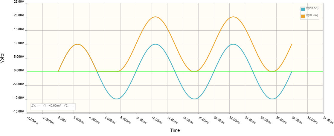
Now for the good stuff. What happens if we start to raise \$V_{IN}\$ again, slowly back to +9V? Remembering that C1 now holds a charge, keeping its lower terminal OUT to be 9V higher in potential than its upper terminal IN, then by raising \$V_{IN}\$ we also raise \$V_{OUT}\$. OUT will follow IN, but always 9V higher in potential. Algebraically:
$$ V_{OUT} = V_{IN} - V_{C1} = V_{IN} - (-9V) = V_{IN} + 9V $$
Critically, since as we raise \$V_{IN}\$ we are also causing \$V_{OUT}\$ to rise above 0V, diode D1 becomes reverse biased, passing no current. With no current through C1, its charge and potential difference remain constant at \$V_{C1} = -9V\$. In fact, this will be the case the whole time \$V_{OUT}\$ remains above 0V. Effectively, C1 is now "level-shifting", always adding 9V to \$V_{IN}\$. I reiterate:
$$ V_{OUT} = V_{IN} + 9V $$
As long as \$V_{IN}\$ never again falls below −9V:
\$V_{OUT}\$ can never fall below 0V
the diode can never become forward biased
no current can ever flow
\$V_{C1}\$ cannot change
Input/output relationship remains \$V_{OUT} = V_{IN} + 9V\$
As long as \$V_{IN}\$ never again falls below −9V, this circuit will "elevate" the input signal potential by 9V, such that it never goes negative. That is how this circuit "restores DC". That is how the output will be a copy of the input, but sitting upon the horizontal 0V axis on a graph.
The purpose of the resistor in your original circuit is to discharge the capacitor slowly, so that the circuit can (over the long term) adapt to keep the output "troughs" sitting on 0V, even as input amplitude changes.

