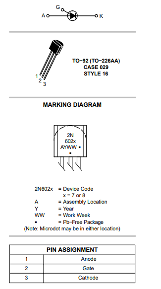
While trying to learn more about electronics and oscillators, I encountered the following post on this forum PUT relaxation oscillator doesn't work. I decided that I would build the circuit which "jonk" suggested in an answer to that post, but instead of a 12 V design I adjusted it to a 5 V design.
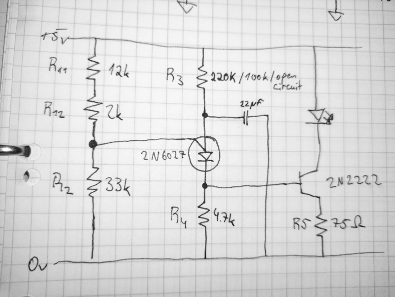
You can see my circuit, which I implemented with real hardware, in the following image:
PUT relaxation oscillator circuit for 5V supply:
When I connect this circuit to power, the LED turns on and stays on. It doesn't oscillate.
The voltage divider is constructed such that its output should be at 3.5 V. When measured isolated, this turns out to be true. When it is connected to the rest of the circuit, it drops to 0.6 V.
Does the gate of the 2N6027 draw too much current from the high resistance voltage divider?
I measured the current going through it, it is about 2.5 microampere, so this shouldn't be the problem, I believe. Still, I tried swapping the resistors to 10k and 22k respectively, which didn't seem to make much of a difference at all.
Then I thought that it might be possible that the current through the PUTs anode to cathode never falls under the valley current, which is necessary to reset it.
Since the Thevenin resistance of the voltage divider is about 10k, I expect the V-current to be about 70 microamperes, so R4 has to be greater than 71429 ohms, so I tried 75k, 100k, 220k and even removing the resistor R4 completely, so approaching infinite ohms. In all four cases the LED stayed on.
At that point I thought something was broken so I swapped the PUT with a new one. This resulted in the voltage at the gate to rise to 1.6 V, which left me with even more questions, which is why I decided to ask you guys.
- Why is the LED not turning off, even when I remove R3 completely, meaning that R3 approaches infinite ohms?
- Why does the voltage at the vate of the 2N6027 not stay at the voltage provided by the voltage divider?
- What can I try to make the oscillator oscillate?
Edit--------------------------------------------------------------
I have tried to check every component of the circuit and measured additional voltages which I have listed below:
Complete circuit:
- V drop across R11 and R12 in series: 3.45V
- V drop across R2: 1.53V
- V across capacitor: 1.46V
- V across across R3: 3.53V
- V 2N6027 gate to ground: 1.53V
- V 2N6027 anode to cathode: 0.52V
- V drop across R4: 0.93V
- V drop across R5: 0.28V
- V drop across the red LED: 1.87V
- V across 2N2222 collector to emitter: 2.83V
- V from 2N2222 gate to ground: 0.93V (shouldnt this be 0.6V to 0.8V?)
After measuring these values, i removed the 2N2222, LED and R5. Instead i connected an oscilloscope, which showed no oscillations. I reconnected the 2N2222, LED and R5 and instead removed the voltage divider, so that 0 V was applied to the Gate of the PUT. Then i measured following voltages:
- V across capacitor: 1.86V
- V across R3: 3.14V
- V 2N6027 anode to cathode: 1.9V
- V across R4: 0V
Shouldnt the PUT be conducting, since the gate voltage is equal to 0 and the anode voltage is higher than 0V + peak point voltage? I would really like to find out why the circuit isnt oscillating, so thanks to everyone who has answered and thanks to everyone who will answer.


