0
\$\begingroup\$

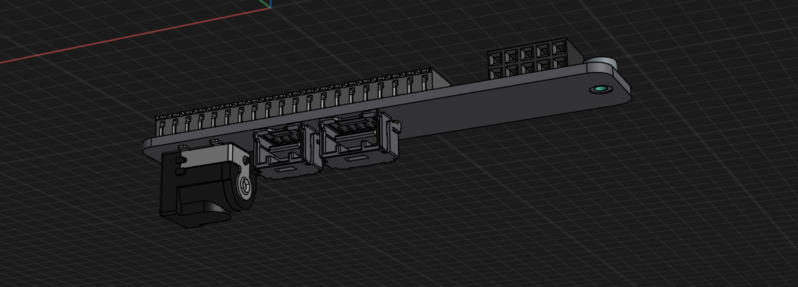
I have this rough layout for a design with some serious space constraints:

PCB 3D View

It has connectors on both sides and the layout rules out through-hole soldering. I only have access to a Hakko IR preheater for SMD soldering, which will require low-temp paste for both sides. I'm worried about the bottom-side components falling off as the contact pads are very small and I doubt I can rely on surface tension to hold things in place. Suitable glue is very hard to find.

I was thinking about splitting up the design into two parallel boards flat against each other. Something like this:

Dual Board Layout

I could join the boards with a few plated throughholes, pieces of solid core wire, and solder on both sides. I only need to get four traces across so this seems easy - but then again, I am out of my depth here.

  • Any easy advice for doing this with one board? I looked at glue datasheets and availability all morning, and nothing feasible came up.

  • If I was to use two boards, any caveats someone new to the field might miss? Would reasonable mechanical strength be achieved by using, say, 6 PTH joints? Should I leave the bottom sides of both boards (the ones facing each other) blank, or could I use them as a common ground plane if electrically joined with multiple connections?

In case it matters, I'll have some smaller components (flyback diodes, a fuse, a couple of ceramic capacitors) on the boards; these are not shown on the CAD design.

\$\endgroup\$
10
  • \$\begingroup\$ What volume do you need this in? Is hand soldering one side an option? \$\endgroup\$ Commented Jul 25 at 16:51
  • \$\begingroup\$ @ChintalagiriShashank The board is 81mm in length. Do you mean hand-soldering the SMD components? I suppose the upward-facing side could be soldered like that, at least in theory. There are no contact pads underneath those connectors (unlike on the other side), but the pads that do exist are positively tiny and I don't have much experience. \$\endgroup\$
    – martona
    Commented Jul 25 at 17:00
  • \$\begingroup\$ I only see two heights on each side (maybe one on the top). Maybe you could reflow the top connectors, flip the board so that the parts sit on a surface (shim one up a bit if necessary, with Kapton tape on the surface, for example) and reflow the other side. If there are small components not shown (like capacitors) surface tension will hold them. \$\endgroup\$ Commented Jul 25 at 17:05
  • \$\begingroup\$ @martona Yes. You'd pick the side with less hard-to-solder components to do by hand. None of the components should have fully hidden pins, like BGAs or Connectors whose pins are entirely under them. With some practice and a temperature controlled soldering iron with a good tip, most SMD components can be hand soldered. It does take patience and time, though. Also, when I ask about volume, I mean the number of boards. If its just a few, you can consider either hand soldering or attaching two PCBs, Personally, I'd not suggest trying to attach two PCBs. \$\endgroup\$ Commented Jul 25 at 17:05
  • \$\begingroup\$ They make adhesives specifically for holding components to the board while reflowing the opposite side. You don't need it for light components like small passives, but for anything you're worried about falling off, just put a dab of high-temp adhesive underneath the body before you reflow it. \$\endgroup\$
    – Hearth
    Commented Jul 25 at 18:35

0

Your Answer

By clicking “Post Your Answer”, you agree to our terms of service and acknowledge you have read our privacy policy.

Browse other questions tagged or ask your own question.