If you are really interested in compensating for the influence of non-ideal components on the filter function, then I would like to recommend TWO DIFFERENT METHODS.
This involves using one of the well-known circuit simulation programs (with a realistic opamp model).
FIRST METHOD
This method compensates for both (numerically known) deviations of the passive components from the calculated (ideal) values as well as non-ideal opamp characteristics (finite GBW, finite input and output impedances).
This method makes use of the substitution theorem of network theory.
As a result, one of the calculated passive components is replaced by a suitable series or parallel resistor-capacitor combination
Reference:
https://www.researchgate.net/publication/301198883_On_Computer-Aided_Optimization_of_RC-Active_Filter_Designs
SECOND METHOD
Here are the basic steps for compensating transfer function errors
caused by parasitics and other non-idealities of active and passive devices.
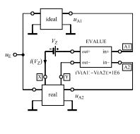
1.) Create two circuits (PSpice: Schematic entry )in one single input file for simulation:
(a) with ideal components, (b) with real components and parasitics.
2.) Drive both circuits (real and ideal) with a common ac input signal (see remark).
3.) Connect both opamp outputs to the differential input nodes of a ideal high-gain amplifier block E_value (with differential input and output).
4.) Select one suitable passive part X (resistor,capacitor) from the real circuit and replace this part by connecting the differential output of the E-block to the two open nodes (X and Y, see diagram).
5) Perform an ac analysis of the whole system in the vicinity of the pole frequency fp (see remark).
6.) The negative feedback causes the differential input voltage of E to be nearly zero (that means:Both output signals of the circuits are nearly equal).
7.) For any frequency to be selected you can use some special formulas to calculate the values of a new complex impedance (R-C seriesor R-C parallel) which should be used to replace the removed passive part X.
8.) Result: At the selected frequency (recommended: pole frequency fp) , both circuit outputs (real and ideal) now are equal. Up to a certain degree, this corrects the whole transfer function.
Remark:
This compensation method was used with good results to correct the
transfer function of active filters for relatively high pole frequencies (non-idealities of the opamp and aditional capacitive parasitics).
For this purpose, the method can be applied to both input-output transfer functions of the closed-loop filter functions.
However, it is strongly recommended to apply the optimization procedure to the LOOP GAIN functions (instead of the closed-loop filter function). In this case, the source ue (see diagram) is to be replaced by the test voltage injected into the open loop ("normal" filter input grounded).
As a result, both loop gain functions (real and ideal) could be made identical at the pole frequency fp. More than that, in this case also the desired transfer functions of both filters (real and ideal) are very close to each other (not only at the pole frequency).

Here are the formulas to be used (for defining corresponding macros):
A) Definitions:
ur=R[V(Y)-V(X)] ; ui=IMG[V(Y)-V(X)] ;
ir=R[i(Vz)] ; ii=IMG[i(Vz)]
B) Correction with Rs-Cs series:
Rs = (ur * ir + ui * ii) / (ir * ir + ii * ii)
Cs = (ir * ir + ii * ii) / [wp * (ur * ii - ui * ir)]
C) Correction with Rp-Cp parallel:
Rp = (ur * ur + ui * ui) / (ur * ir + ui * ii)
Cp = (ur * ii - ui * ir) / [wp * (ur * ur + ui * ui)]
EXAMPLE:
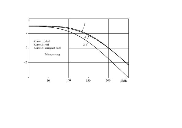
Here are the results after applying the above described method for compensationg the influence of non-dealities (tolerances, parasitics, finite GBW) on the transfer function of a multi-feedback lowpass filter (opamp: AD822).
curve 1: Ideal; curve 2: Real; curve 3: compensated.


