0
\$\begingroup\$

I am a PhD student and completely new to circuit design. I need a compact-sized circuit and prefer not to use an impedance analyzer due to its bulkiness.

I am looking to build a circuit capable of automatically measuring the impedance of a sensor in the range of 1MΩ to 30MΩ. I am unsure how to approach this task, especially with the various methods available for impedance measurement.

I’m not certain which method would be most suitable for automatic measurement in my case. There are different impedance measurement modules, but none seem to have the capability to measure impedance automatically within this range. My sensor’s equivalent circuit is a resistor in parallel with a capacitor.

Could someone guide me through the procedure to build the circuit design? Specifically, I would like to know which components I should purchase to begin building the circuit. If there are any tutorials or resources that you could recommend, that would be very helpful as well.

So far, I have only completed the integration of a direct digital synthesis (DDS) with an Arduino to generate a signal with a frequency of 1 kHz and an amplitude of 500mV, which meets my signal requirements. I am uncertain about how to proceed with the remaining circuit design.

\$\endgroup\$
5
  • \$\begingroup\$ Have tried RLC meter designs at 10 kHz? 1MHz? \$\endgroup\$
    – D.A.S.
    Commented Aug 10 at 1:11
  • \$\begingroup\$ The sensor's model is a capacitor and a resistor. These are orthogonal, so writing impedance between 1 and 30 meg isn't entirely clear about the capacitance range and the resistance range. Can you add more detail? \$\endgroup\$ Commented Aug 10 at 1:26
  • \$\begingroup\$ To measure the capacitive impedance (in practice of the R-C parallel) the De Sauty bridge is used. To automate it the step seems simple to me using a microcontroller and some OpAmps to vary the known capacity of the bridge. \$\endgroup\$ Commented Aug 10 at 7:27
  • \$\begingroup\$ What is the physical form-factor required for this apparatus? Eg: benchtop, standalone field ruggedised, or co-located within another apparatus? What is the available power source, eg: mains AC, battery, or DC from another apparatus? What is the use-case, eg: manual operation on a bench, or automatic periodic operation within another apparatus? \$\endgroup\$ Commented Aug 10 at 22:16
  • \$\begingroup\$ What is the precision & accuracy required, eg: within 1%, or parts-per-million? Will it be used in a temperature & humidity controlled environment? \$\endgroup\$ Commented Aug 10 at 22:17

2 Answers 2

-1
\$\begingroup\$

The upper shown approach is good to with, you can design this simple circuit in terms to calculate the impedance parameters easily. Btw, Arduino has only 10 bit ADC keep that in mind, I will suggest to go with external ADS1115 16 bit.

\$\endgroup\$
1
  • \$\begingroup\$ This sir Thanks a lot for the explanation, I will use this approach to measure the impedance, \$\endgroup\$ Commented Aug 12 at 15:17
0
\$\begingroup\$

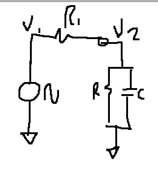
Basically you have to supply a (sinusoidal) signal and measure the ratio of voltage applied to current flowing. This can be done with your Arduino, some opamps and some calculations.

For an example using an oscilloscope see https://github.com/jp3141/Vector-Network-Analyzer

VNA setup

Using this circuit, you need to measure V1 and V2. The current is (V1-V2)/R, and the voltage on the load is V2. These measurements and calculations are of complex quantities (i.e. real and imaginary parts). Basically, measure the values multiple times per cycle (say at > 10x the sinusoid frequency). Calculate the phase angle. Do the same for V2. You'll need to understand the concepts between real and imaginary signals to convert your ADC measurements to magnitude and phase and to complete these calculations.

With 30 MΩ, parasitic resistance and possibly capacitance will affect your accuracy. If you measure with NO load connected (i.e. just the parasitics), you can calculate that value, and then subtract it from your measurement with the load.

\$\endgroup\$
3
  • \$\begingroup\$ As the nature of the DUT (R||C) is already known, only the magnitude of R and X has to be calculated. To do that you get by with scalar voltage measurements and without using complex numbers. \$\endgroup\$
    – Raonoke
    Commented Aug 10 at 8:37
  • \$\begingroup\$ Not correct. You can't determine both R & C from just a single magnitude measurement. All you could determine is the magnitude of Z, but not phase. \$\endgroup\$
    – jp314
    Commented Aug 10 at 16:01
  • \$\begingroup\$ In case you missed it, I wrote measurements. Three to be exact. \$\endgroup\$
    – Raonoke
    Commented Aug 10 at 17:33

Your Answer

By clicking “Post Your Answer”, you agree to our terms of service and acknowledge you have read our privacy policy.

Not the answer you're looking for? Browse other questions tagged or ask your own question.