0
\$\begingroup\$

I am analysing the input impedance of a capacitive amplifier as shown below in fig 1 and 2. The two circuits are identical except at the input. Fig1 has two differential voltage sources and Fig2 has one voltage source and a ground for the other input.

To measure the input impedance, this is what I did for both cases:

Fig1: Zin = (V1P - V1N) / (I2 - I3).

Fig2: Zin = V2P / I4.

Since the opamp creates virtual grounds at the bottom plates of input capacitors, I expect to see the Zin of both Fig1 and Fig2 be the same and equal to the impedance of input capacitor. However, from the simulation results below, fig2 seems to have a different conclusion.

Fig1: Capacitive Amplifier with Fully-Differential Inputs enter image description here
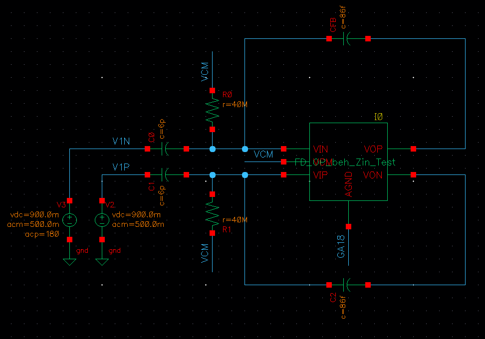
Fig2: Capacitive Amplifier with Single-Ended Input enter image description here
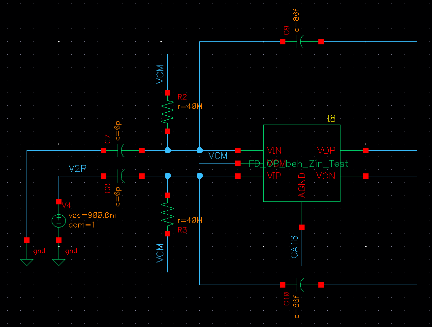
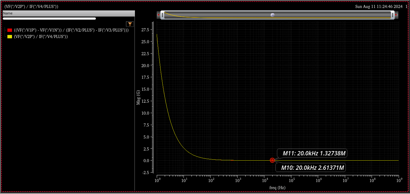
Simulations (analyzed at 20kHz): Zin_Fig1 = 1.327 Mohm, Zin_Fig2 = 2.614 Mohm

enter image description here

Could someone please show me why there is a discrepancy in Fig2 input impedance?

Thank you very much

\$\endgroup\$
6
  • 1
    \$\begingroup\$ This should be no different to a fully differential amp with resistors. Differentially you have a virtual short between the +/- inputs of the amplifier which means the input impedance would be two 6pF caps in series or 2.653 MOhm @ 20kHz. In single ended mode, the input impedance converges to 2.653 MOhm @ 20kHz (6pF/2) for gain aproaching infinity and 1.326MOhm @ 20kHz (6pF) with gain aproaching zero. Your gain is far from infinity but still large so the 2.6137 MOhm in single ended mode looks right. \$\endgroup\$
    – Raonoke
    Commented Aug 11 at 18:18
  • \$\begingroup\$ @Raonoke Thank you very much for your reply. I have a question here. Is my way of calculating Zin for the differential mode correct (Zin = (V1P - V1N) / (I2 - I3) )? V1P and V1N are 0.5V ac magnitude and 180 deg out of phase. I2 and I3 are the current drawn from the sources. \$\endgroup\$
    – Kenlucius
    Commented Aug 12 at 14:08
  • 1
    \$\begingroup\$ The problem I see is in the denominator of Zin. As the two 6p caps are virtually shorted (not grounded), I2 and I3 is actually the same current just with opposite direction. What you have is I - (-I) = 2I and as a result the plot shows only 1/2 Zin. On a side note, for normal operation, a 0.5V AC input voltage is rather high considering the large gain of the amplifier and the 1.8V DC supply voltage. \$\endgroup\$
    – Raonoke
    Commented Aug 12 at 15:30
  • \$\begingroup\$ @Raonoke Thank you very much for your reply. So, for the Differential Mode (Fig1), what I should correct for Zin is the denominator part because the two caps are virtually shorted and, therefore, equivalently two caps in series from the input ports' point of view. Therefore: Zin = (V1P - V1N) / I2. Is the explanation correct? To extend the idea. Let's look at the resistive fully differential amplifier in your first comment. The Zin in that circuit would be 2*Rin, where Rin is the input resistor of the amplifier circuit. Could you please help me see if these two understandings are correct? \$\endgroup\$
    – Kenlucius
    Commented Aug 13 at 2:50
  • 1
    \$\begingroup\$ Use either I2 or I3 to plot Zin. With differential input Zin = 2 * Xcin for the fully diff amp version with caps and Zin = 2 * Rin for the version with resistors. \$\endgroup\$
    – Raonoke
    Commented Aug 13 at 23:11

1 Answer 1

2
\$\begingroup\$

What are the DC voltages at the input to the amplifier? With a 40 Mohm resistor, the DC level may be out of the common mode range of the amplifier unless you're using a FET input amplifier.

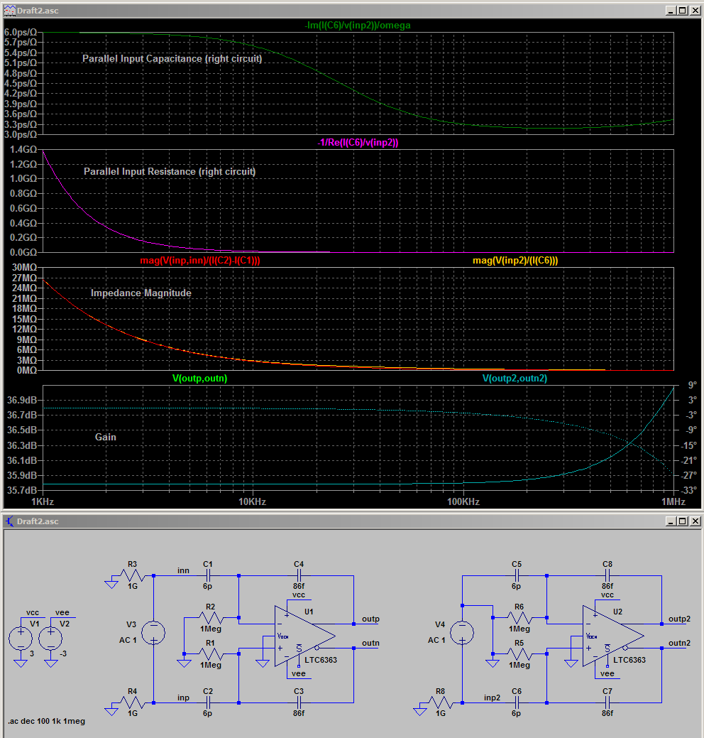
I did a similar simulation in LTspice using your math. Both configurations give 1.32 Mohm impedance magnitude at 20 kHz.

DiffAmpImpedance

Perhaps more details of the simulator you're using, the device, and power supply voltages would be useful in sussing out your issues.

[Edit]
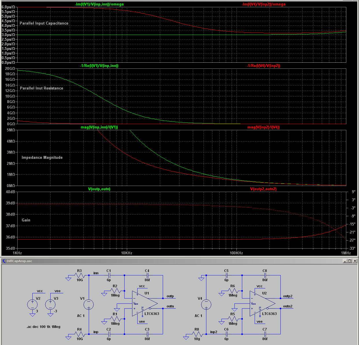
Some after thoughts, the current through the input capacitors isn't I(C1)-I(C2) in the impedance equation since it's the same current, but out of phase (you are effectively doubling the current, or, halving the impedance). Below uses the current supplied by the source. The simulation shows that above 10 kHz things are veering away from ideal due to the differential amplifier characteristics as seen in the parallel input resistance and capacitance.

DiffAmp

\$\endgroup\$
2
  • \$\begingroup\$ Both Zin don't look right. In fully differential mode vou actually take twice the input current to calculate Zin. Looks like the OP makes the same error. The virtual short between the two 6pF input caps puts them in series and makes Zin = 3pF respectively 2.653 MOhm @ 20kHz. In single ended mode the low value Vcm resistors (1 MOhm) seem to impact Zin. Does Zin change if you raise both resistors to 100 MOhm? A fully differential CMOS op amp would be convenient but I don't have an example on hand. \$\endgroup\$
    – Raonoke
    Commented Aug 11 at 19:30
  • \$\begingroup\$ @ qrk. Thank you for your reply. This is the information for my circuit. Power = 1.8 V. VCM = 0.9 V. The OP is simply a model for MOS OP and has a large open-loop gain (100 dB). Is my way of calculating the Zin for the differential mode correct? Zin = (V1P - V1N) / (I2 - I3). Here V1P and V1N are both 0.5 ac magnitude and are 180 deg out of phase. I2 and I3 are the currents drawn from the input sources as in Fig1 of my post. \$\endgroup\$
    – Kenlucius
    Commented Aug 12 at 14:22

Your Answer

By clicking “Post Your Answer”, you agree to our terms of service and acknowledge you have read our privacy policy.

Not the answer you're looking for? Browse other questions tagged or ask your own question.