1
\$\begingroup\$

I have one hx711 module connected a 200 kg load cell and I'm measuring a high current consumption: around 13mA where the datasheet says it should be around 1mA.

Cabling is as follows: usb to the mcu (around 4.9V), mcu raw/gnd to the module Vcc/Gnd and data/clock pin to some consecutive pins on the mcu. Load cell black to hx711 E+, white E-, red A+, green A-. I can read the values fine and accurately. I have 4 load cells bought together on Aliexpress (specs below).

Here are the things I tried which didn't had any effect (high current):

  • tried each 4 load cell separately.
  • tried channel B but couldn't read any meaningful value
  • tried different microcontroller: pro micro and esp32.
  • tried different library: RobTillaart/HX711 and MajicDesigns/MD_HX711.
  • tried the hx711 modules from berrybase.ch (trusted) and my own design (based on Sparkfun).

Load cell: load cell Berrybase module looks as the usual "cheap" hx711 module module I wasn't able to try different types of load cells yet.
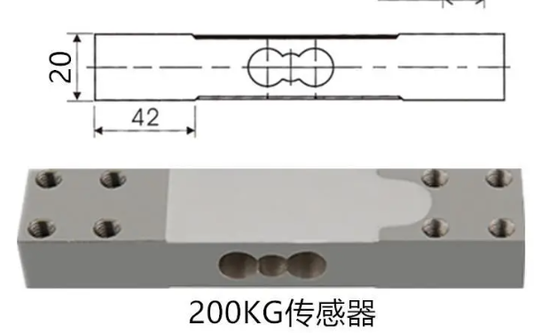
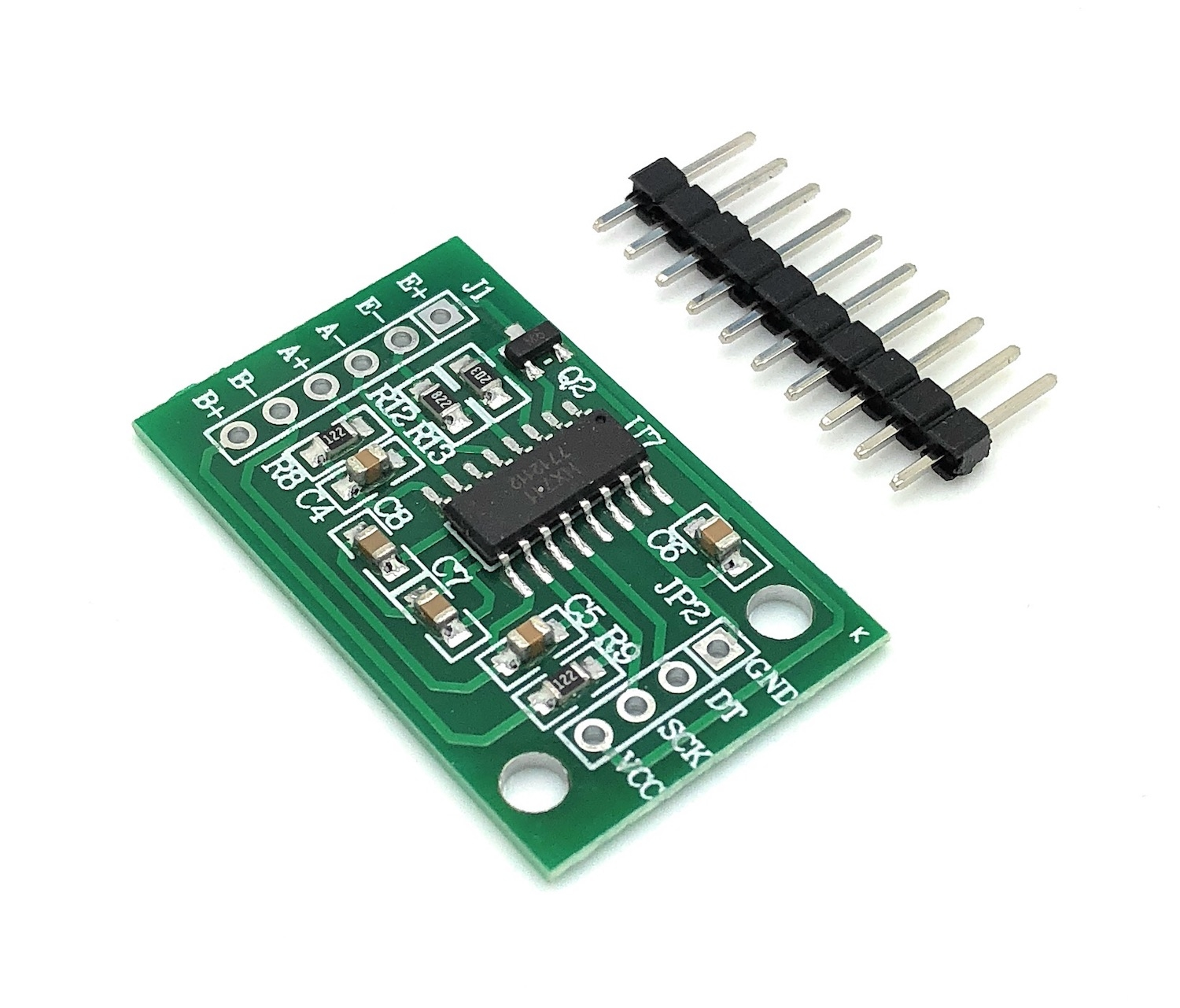
Here are measurements I have done myself on pro micro with berrybase module: R between white-black is ~380 ohm, green-red is ~330 ohm. Current consumption taken between pin RAW and the module Vcc is 13mA except when it's in sleep (power_down) it's 0uA (cannot measure). If I unplug the load cell but still active, it's around 1.8mA. Measuring current on E+ is ~10mA, where for A+/A- I cannot measure it's 0mA. I have some voltage measurements too if that can help.

At this point I'm unsure where is the issue even after trying so many things, should I suspect a problem with the load cell themselves? I'm also concerned about the load cell wiring as the colors don't look standard but this is what the seller wrote and I can read values fine and accurately (is that something to question?).

Here are the specifications of the load cell provided by the Aliexpress seller (if that helps): Input Impedance :405 10 Output impedance :350 3 Insulation resistance :5000M (100VDC) Excitation voltage :5VDC ~ 10VDC

MAX working voltage :12VDC Temperature compensation range :10 ~ +40 Operating temperature range: -20 ~ +60 Temperature effect on zero 0.03% F.S/10 Temmp.effect 0.02% F.S/10

\$\endgroup\$

2 Answers 2

1
\$\begingroup\$

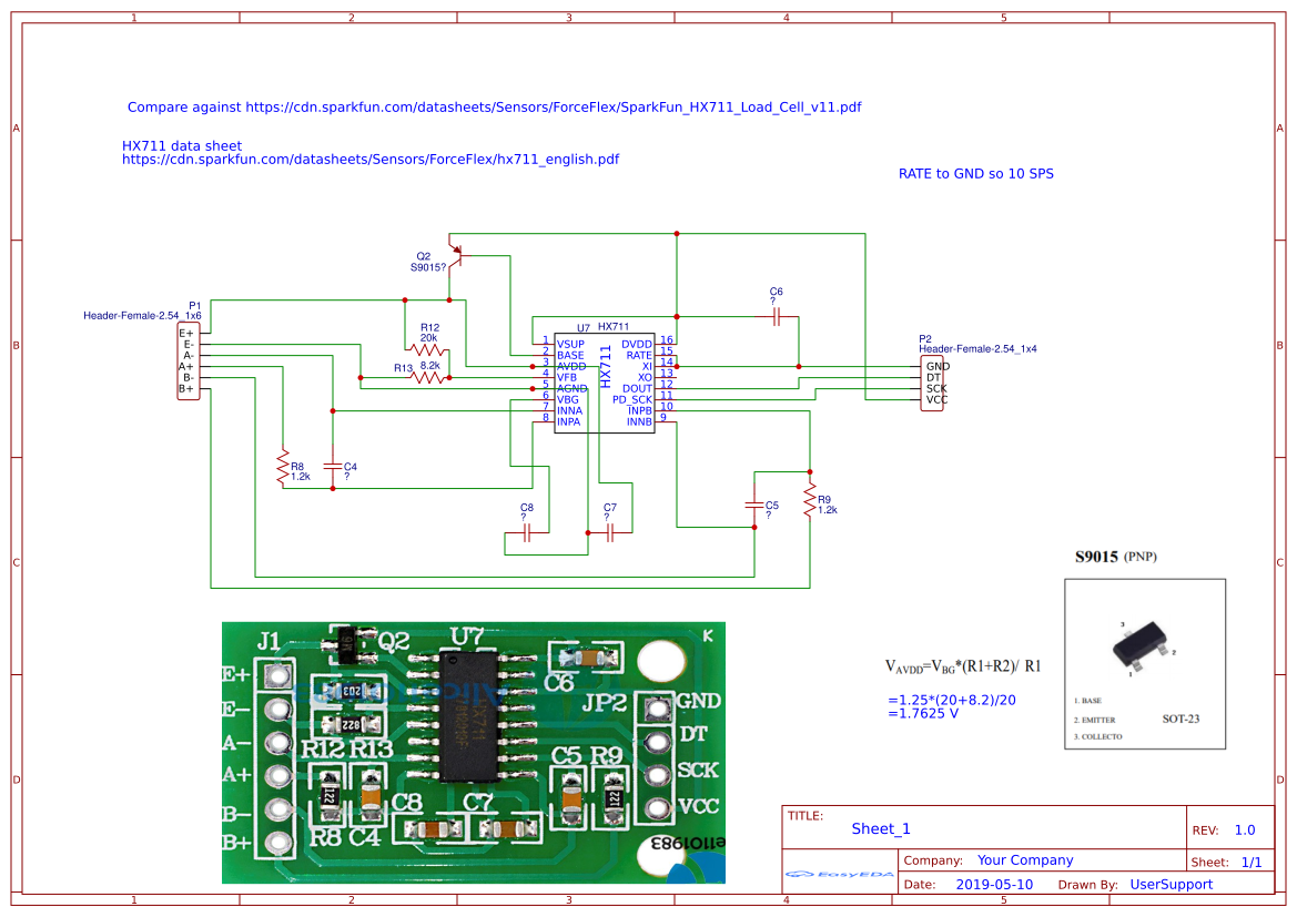
Have a look at the typical module schematic from here (the equation for the excitation voltage is obviously incorrect):

enter image description here

And the Avia chip datasheet from here.

enter image description here

Digital supply current 0.1mA (typical)

Analog supply current 1.4mA (typical)

Regulator divider using 8.2k/20k divider - 1.25V/8.2kΩ = 0.15mA (typical)

Excitation voltage: 1.25V*(20kΩ+8.2kΩ)/8.2kΩ= 4.3V (typical)

Load cell current: 4.3V/350Ω = 11.9mA (typical)

Total: 13.55mA typical (active) with load cell connected

Total: 1.65mA typical (active) with load cell disconnected

\$\endgroup\$
2
  • \$\begingroup\$ Thanks. I understand both Kartman and you suggest this is perfectly normal due to Ohm law with the low resistance of those load cells. For completeness let me ask if (1) those resistance values are usual for load cells? They're low! (2) What if I add 10K resistances between load cell and hx711, that should lower consumption? \$\endgroup\$
    – Axel Angel
    Commented Aug 13 at 16:31
  • \$\begingroup\$ Yes, it is standard for metal strain gauges. If you reduce the excitation voltage (say by changing the resistor ratio for the regulator) the already very low signal levels will be proportionally reduced and noise and drift will be proportionally more significant. A 30:1 reduction would be catastrophic. You want to regulate the voltage on the load cell because adding a resistor would introduce a scale error term from the difference in tempcos. \$\endgroup\$ Commented Aug 14 at 1:07
0
\$\begingroup\$

If we apply some Ohm’s law, the reason becomes clear. The load cell excitation is specified as 350 Ohms. Your excitation voltage is 5V. I = V/R = 5/350 = ~0.014A or 14mA. Which is close to your measurement of 13mA.

If you’re concerned about the power consumption, a common method is to only power the loadcell when you want to make a measurement. There are other techniques using AC excitation, but that is a new level of complexity.

\$\endgroup\$
2
  • \$\begingroup\$ I cannot upvote but I would like to show my appreciation for your reply. Thank you \$\endgroup\$
    – Axel Angel
    Commented Aug 13 at 16:33
  • \$\begingroup\$ Spehro did a more complete response. 350 Ohm is standard for most load cells. You can get higher resistance ones like 1or 2k, but the sensitivity can be less. As Spehro mentions, you’re dealing with small voltages so thermal effects like thermocouples due to dissimilar metals in your connections can come into play. Don’t be fooled by the apparent simplicity. \$\endgroup\$
    – Kartman
    Commented Aug 14 at 6:35

Your Answer

By clicking “Post Your Answer”, you agree to our terms of service and acknowledge you have read our privacy policy.

Not the answer you're looking for? Browse other questions tagged or ask your own question.