Update (21.Aug.2024): from the answers I learned that the bias current should be only some pico ampere. But in my case, this is micro ampere. It turns out that either the components are broken, or they are counterfeit.
Please comment below if you think there could be other reasons.

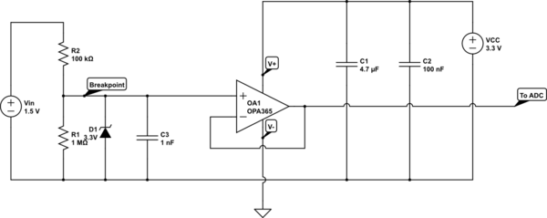
simulate this circuit – Schematic created using CircuitLab
I'm learning to use a voltage follower as a buffer for my DC voltage measurement. The simulation figure below only shows the schematic. But I'm doing tests with a real system.
The component is an OP Amp (TLVx365 / OPA365) and the output pin is directly connected to the negative input pin. The power supply is a positive 3.3V single-supply.
In theory, the input impedance is very large / infinite. However, when I measured it with a multimeter, it shows that the input impedance is only around 1 or 2 hundred of kilo ohms.
I want to ask here, how can I estimate the input impedance of this voltage follower from the datasheet of the opamp?
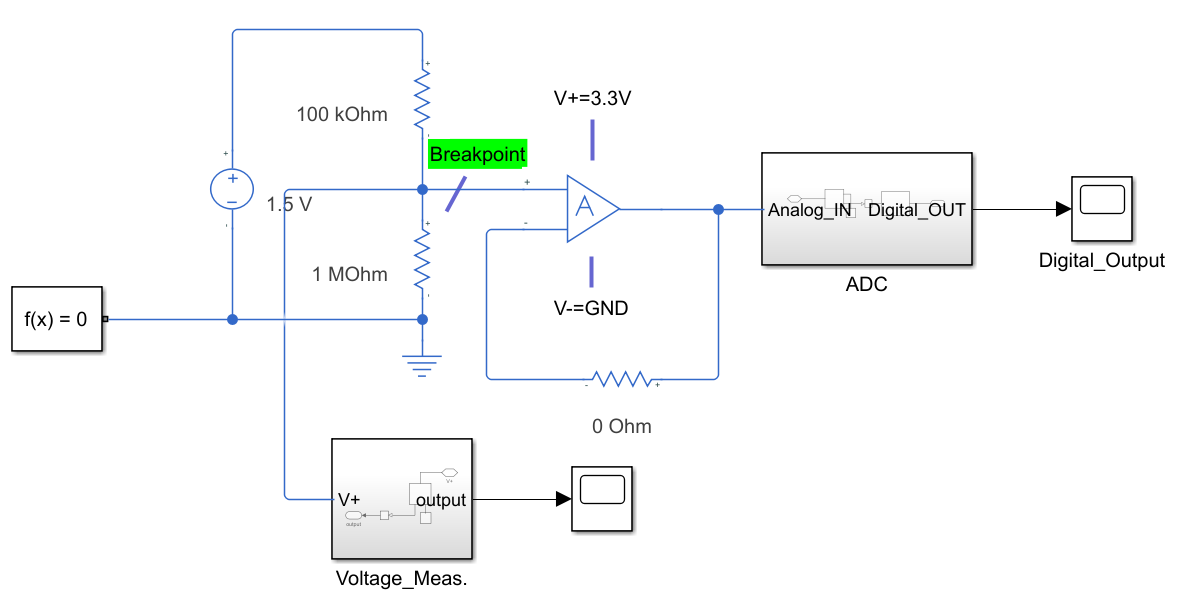
I made this figure with simulink. Hopefully, it can show my measurment method. I can connect or disconnect the "breakpoint" so that the influence from the buffer (voltage follower) can be noticed by measuring the voltage at this breakpoint. The result: with 1.5V VCC over the two resistors, the voltage at the breakpoint was 1.326V without connecting the buffer. It dropped to 0.3V after connecting the buffer. So I can estimate this impedance by calculating the parallelled resistor. It's around 26k Ohm.
The input current can also be measured by the multimeter: it rised from 1.76 uA to around 12 uA. This result can also show that the buffer input impedance is about 26k.
Now I'm not sure if I can ignore the effect of the ADC.


