2
\$\begingroup\$

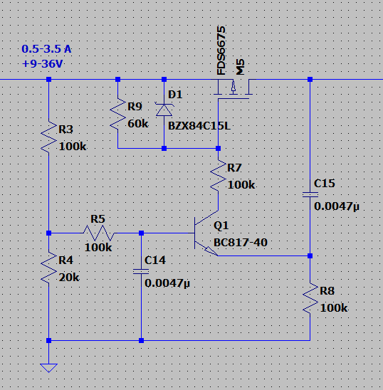
I have a DCDC Buck-Boost converter circuit that needs inrush protection. I have looked around the internet and the resources for a viable solution and decided to use the following circuit from this answer to a similar question. My circuit is:

enter image description here

The input is 9-36V DC and the current may vary between a wide range of 0.5A and ~3.5A (different modes of operation). I have simulated this circuit with a MOS that was available in LTspice though I am planning on buying a different one.

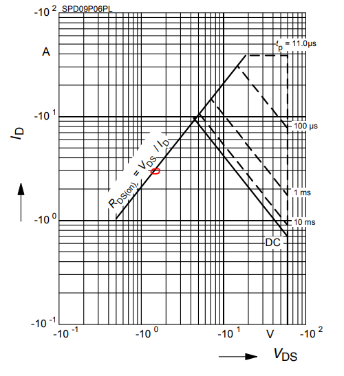
What I am worried about is the SOA's of the MOSFET's. Most FET's declare a drain current that seems suitable for my application, however the MOS will be fully on after it limits the inrush current. This will make the Vds fairly small and that leaves my operating current levels outside of the SOA's.

How should I approach this situation? I believe the SOA's are to be trusted and I may destroy my MOS if I operate it fully on with such high currents but there might be something I am missing because inrush limiting in DCDC converters is not something new.

Extra question for those interested: PMOS in my case is normally on in the simulation since its Vg is slightly less than its Vs (I think). This causes a small inrush leak. The MOS instantly turns off and slowly opens with the help of the feedback capacitor C15 and the turning on of Q1. Does this make sense or is it something that happens in a simulation environment?

Edit: The load can be approximated to a parallel RC with R = 45-50ohms and C = 270-300uF. The converter has a soft-start capability and I can be flexible with it. Right now, it is set to around 30ms. The main part or the inrush that I am observing happens between 1.2-3ms. The input of the DC-DC block also has a 3rd order EMI filter. The capacitance of it is included in the approximation but the inductance is not. It is around 7.3uH.

Thanks in advance for your attention and answers!

Arbitrary PMOS SOA example: https://www.infineon.com/dgdl/SPD09P06PL+Rev2.5.pdf?folderId=db3a30431ed1d7b2011f4042f2ff4ec5&fileId=db3a30431ed1d7b2011f40486c6a4ed4

\$\endgroup\$
13
  • \$\begingroup\$ Is it supposed to limit the inrush current to the input caps of the DC-DC converter, or something else? \$\endgroup\$
    – bobflux
    Commented Aug 22 at 13:22
  • \$\begingroup\$ Yeah. The input capacitors of the converter are located to the right of the figure. The input is directly (after TVS, reverse polarity protection, etc.) connected to the input source. \$\endgroup\$ Commented Aug 22 at 13:34
  • \$\begingroup\$ It is not clear to me why you think at lower VDS you will violate SOA. Can you explain? \$\endgroup\$
    – sai
    Commented Aug 22 at 14:41
  • \$\begingroup\$ Sure, take a look at the SOA of this PMOS for example. As |VDS| decreases, the drain current limit also decreases due to Rds(on) limitation. In my case, I will be using the MOS nearly fully on, which means its |VDS| will be very low. The maximum current that the MOS in in the link above can pass at VDS < 1V is ~ 1A which is lower than my requirements. I was wondering if this would be an issue. \$\endgroup\$ Commented Aug 22 at 15:07
  • \$\begingroup\$ How much capacitance after the PMOS? Is there something to delay the startup of the DC-DC converter until after the PMOS is fully on? \$\endgroup\$
    – bobflux
    Commented Aug 22 at 16:48

1 Answer 1

2
\$\begingroup\$

From the datasheet that you have added in the question, I pasted below a snapshot of the SOA graph.

SOA graph from the datasheet mentioned in the question

At |VDS| of 500mV, safe operating current is 1A and your use-case is 3A. If I understand right, this is your concern.

In reality, when you have 3A current, VDS will increase to about 1.5V (red circle in the graph). So, it still falls in the SOA. You however have 4.5W power dissipation in the PMOS which you need to take care of by using a heat sink.

\$\endgroup\$
3
  • \$\begingroup\$ Yeah you got it right. Let's use the Rds(on) of the MOS we are already talking on. If I have around 3.5A when the MOS is in the on state, due to Rds(on) = 0.25, I would have around 0.875 V. This corresponds to approximately 0.9A limit on the SOA. Does this not pose an issue? \$\endgroup\$ Commented Aug 23 at 9:43
  • \$\begingroup\$ In the SOA graph, Rds(on) is already taken as 0.5. So, vds will be about 1.65V for 3.5A. \$\endgroup\$
    – sai
    Commented Aug 23 at 11:04
  • \$\begingroup\$ I see. Still, this is something I need to take into account for. Though I think its more clear now. Thank you for your answer. \$\endgroup\$ Commented Aug 23 at 13:04

Your Answer

By clicking “Post Your Answer”, you agree to our terms of service and acknowledge you have read our privacy policy.

Not the answer you're looking for? Browse other questions tagged or ask your own question.