6
\$\begingroup\$

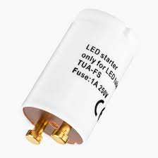
What exactly is LED starter?

enter image description here

The producers ship it with only a vague explanation that it is needed to replace the original fluorescent tube starter when replacing the fluorescent tube with its LED doppelganger, but they never explain what it is inside and how exactly it works.

\$\endgroup\$
3
  • \$\begingroup\$ It doesn't start an LED. It fills in the gap of the fluorescent tube starter, when you are using an LED tube instead of a fluorescent tube. \$\endgroup\$ Commented Aug 26 at 17:18
  • \$\begingroup\$ why should they explain what's inside and how it works? \$\endgroup\$
    – jsotola
    Commented Aug 26 at 17:40
  • 1
    \$\begingroup\$ I see the more serious manufacturers like Hoftronic call it a "dummy starter". \$\endgroup\$
    – Nemo
    Commented Nov 17 at 21:13

2 Answers 2

11
\$\begingroup\$

If you crack it open, you will only find a fuse or short inside it.

The “starter” is a technical misnomer as everything needed to start a LED tube replacement for a fluorescent one is already inside the tube. In order to retrofit it into an existing armature, the starter needs to be replaced with a short (or fuse, depending on local rules). Without it, there is no voltage available to the LED tube driver and with a regular starter, there is nothing to emulate the filament inside the tube to make it flip over, save for a few very specialized LED tube replacements.

Best guess is that they decided to call it a starter to feel familiar with what they are replacing.

\$\endgroup\$
6
  • \$\begingroup\$ Would there be any difficulty, beyond the cost of including and connecting an extra bridge rectifier, with having a bridge rectifier at both ends of the tube, driving common DC rails? That would seem to yield an arrangement that would work with any two pins connected to the AC line, and the other pins shorted, left open, or connected through an "old-style" starter, with no need for a separate starter. \$\endgroup\$
    – supercat
    Commented Aug 26 at 21:57
  • 1
    \$\begingroup\$ @supercat It would make assembling these LED tubes much more complicated (and hence probably more expensive). Right now, one end cap contains the driver and an ordinary LED strip protruding out of it, and one just sticks that into a plastic pipe and closes it with a completely dumb plastic cap on the other end. Having to reliably connect that other end cap to the strip would either require soldering on wires and then somehow making them fold up nicely in the end cap, or using something potentially unreliable like spring contacts. \$\endgroup\$
    – TooTea
    Commented Aug 27 at 7:40
  • \$\begingroup\$ @TooTea: It would increase the cost somewhat, though I was thinking the connector for one end could have spring clips that would allow it to be pushed through the tube and then grab the far end. One would need connections with a tiny bit of "give" to accommodate tolerances in tube length, but the need for the external thing to go in the "starter" socket, which may or may not need a fuse, would be eliminated. \$\endgroup\$
    – supercat
    Commented Aug 27 at 14:44
  • \$\begingroup\$ @supercat That would make tube lightning way more dangerous, as during insertion it is possible that one side is inserted into the socket while you are holding the other side and could be touching the metals pins. Normal tube lightning has a very high resistance at this point, so no electricity flows \$\endgroup\$
    – Ferrybig
    Commented Aug 27 at 15:45
  • \$\begingroup\$ @Ferrybig: Hmm... I'm not sure I'd say "way more dangerous", since on many fixtures it would be possible for one of the pins at one end of the tube to touch fixtures's contact while the other end could still make contact with the user's finger, and I think the cold resistance of a fluorescent-tube filament would allow plenty of current to cause a shock even when using old fluorescent tubes if someone was trying to use their fingers to feel the orientation of the tube pins during insertion; I would think that scenario would if anything be more common than touching pins on the far end. \$\endgroup\$
    – supercat
    Commented Aug 27 at 16:34
4
\$\begingroup\$

The circuit of an old-style florescent fixture with a starter is like this (image from here - corrected by myself):
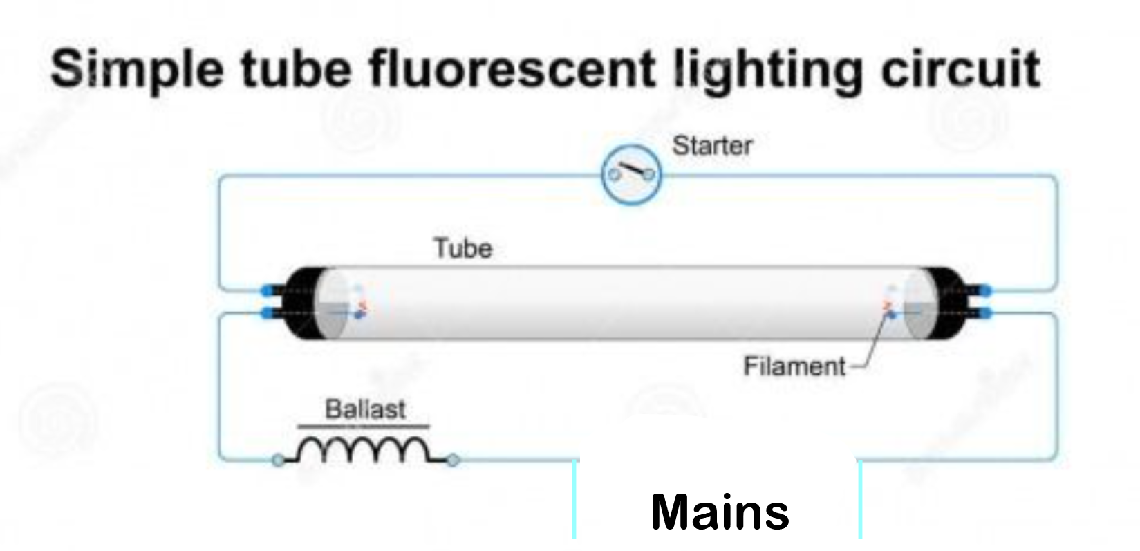
enter image description here

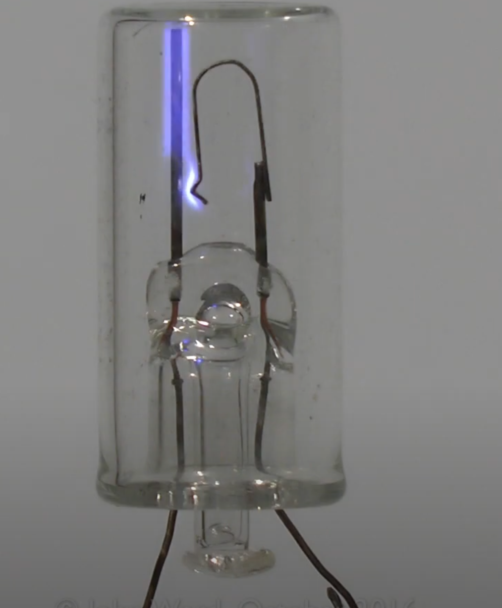
The conventional starter is a special discharge tube with a bimetal switch inside. Image from this video:

When the fluorescent tube is not ignited the voltage across it is high, so the starter gas discharge tube ignites and heats the bimetal so it shorts and then heats the filaments at each end of the tube. That stops the heating of the bimetal so it will release in a short time. Once the filaments are sufficiently heated, there's enough emission to sustain a discharge and they self-heat and the starter can release until the power is cycled. Sometimes it takes a few 'tries' to get the tube to light.

In some cases, they replaced the starter switch with a momentary switch for manual operation (eg. for magnifier circular lamps).
enter image description here

So as you can see there is power available from one end of the tube to the other, even without the starter, so what's up with doing anything with the starter, you may ask.

LED lamps have electronics incorporated and it's inconvenient to run a wire the length of the tube so it would be more convenient to pack the power supply into one end and short the starter socket so that both sides of the power are available on either end. Also if they shorted both ends of the filament pins and drew power from them, it might do something rather unpleasant if the normal starter was still installed (and a percentage of DIY'rs are going to do dumb things).

At least that's my assumption.

Why do they call it a 'starter'? The LED won't work without it, so it must be a starter..

\$\endgroup\$
4
  • 8
    \$\begingroup\$ They call it a starter because it fits in the slot where a starter goes. Not because it actually a starts anything. \$\endgroup\$ Commented Aug 26 at 17:19
  • 2
    \$\begingroup\$ @user20574 That's a good point. 8-/ \$\endgroup\$ Commented Aug 26 at 17:21
  • \$\begingroup\$ Could you please draw how it is wired inside the LED "tube"? I still cannot get the idea. \$\endgroup\$ Commented Sep 2 at 15:10
  • \$\begingroup\$ There are two pins at each end. The two at one end inside the tube go to the usual LED switching power supply with a bunch of components. The two at the other end of the tube are shorted together. \$\endgroup\$ Commented Sep 2 at 15:17

Your Answer

By clicking “Post Your Answer”, you agree to our terms of service and acknowledge you have read our privacy policy.

Not the answer you're looking for? Browse other questions tagged or ask your own question.