0
\$\begingroup\$

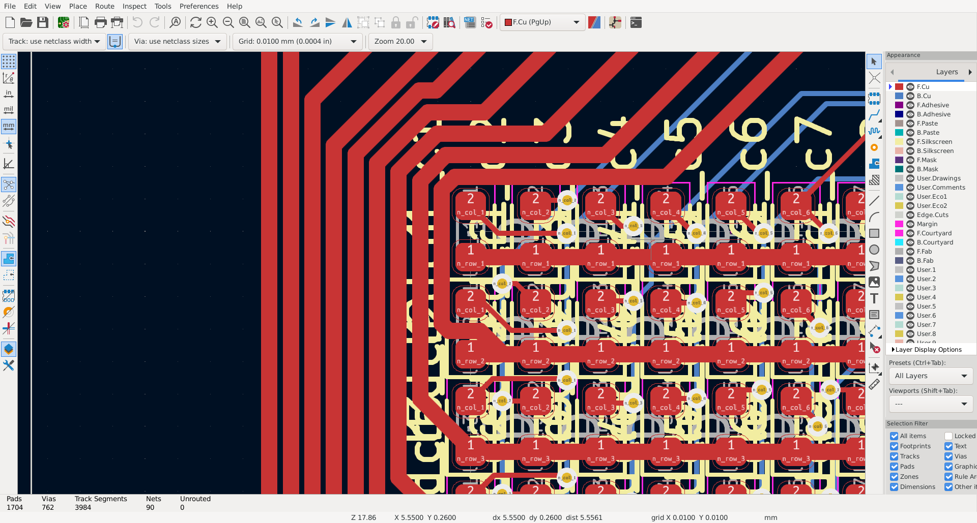
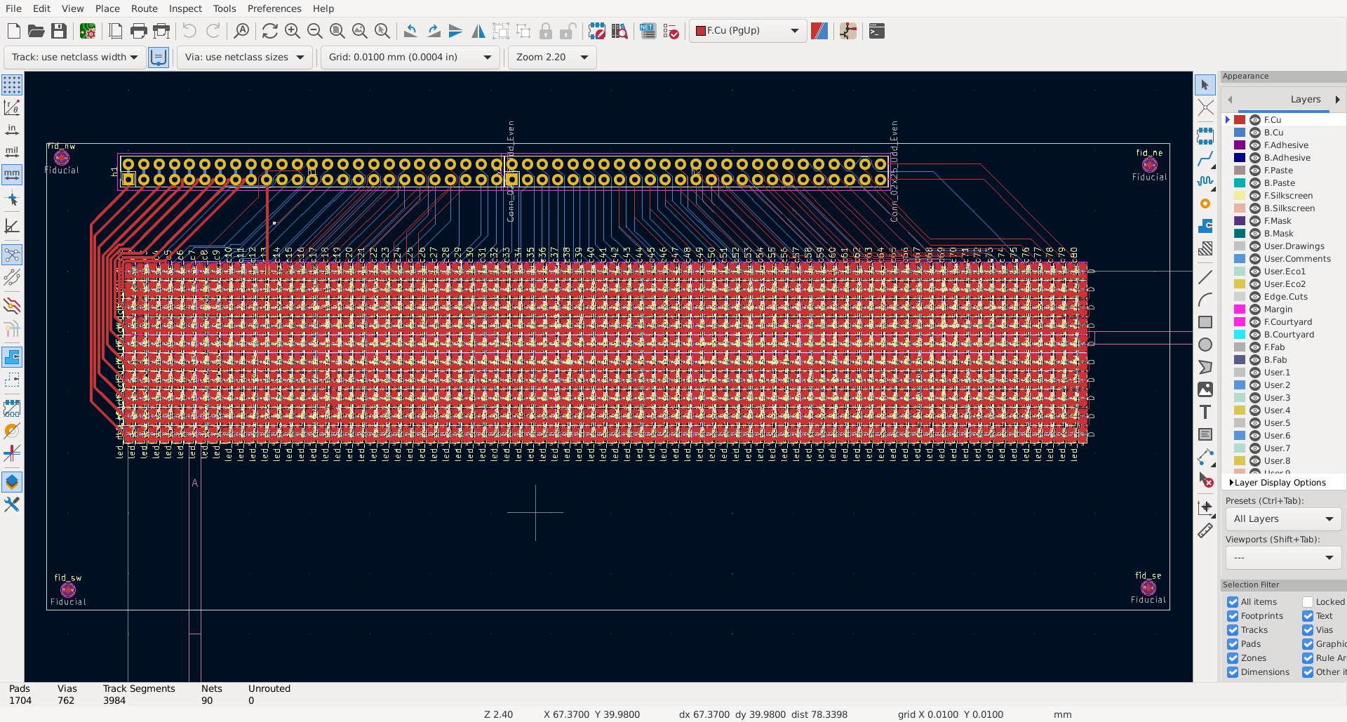
Basically, does the LED matrix PCB board below have a chance to work? If not, how can it be modified to have a chance to work?

The concern is the voltage drop along the row traces. Each row must carry up to 8 A (100 mA per led times 80 columns). That works out to a voltage drop of about 1.3 V assuming typical circuit board construction.

The rows will be strobed by the controller (not shown) so that only one is active at a time. When a row is active, all the appropriate columns are active simultaneously. Thereby, around 10% duty cycle for each LED. The voltage of the drive will be tuned to result in approximately 100 mA current per column (on active columns).

Ideas I've had to counteract the voltage drop:

  • upgrade to 2oz copper weight on the outer layers of the board
  • widen the traces further
  • add series resistors on each column that “emulate” the additional resistance required to reach all of the remaining columns, in order to equalize the voltage seen at each LED

I like the last idea best. Is there a good reason not to do that? Are there any other options worth considering? Is this a real problem that can result in poor yield or performance, or am I worrying too much about the voltage drop?

board1

board2

\$\endgroup\$

1 Answer 1

4
\$\begingroup\$

Rather than incorporate a resistor in each column, redesign the column circuit so that it is a switched constant current drive. That way the track resistance is immaterial and it covers the worse case scenario of all LEDs being on at the same time. Since only one row is active at any time, only one LED per column could be active so current sharing is not an issue.

\$\endgroup\$
3
  • \$\begingroup\$ I'm fairly certain that a resistor per column costs less than a switched constant current drive per column. I appreciate that constant current would also solve the problem of manufacturing variation in the LEDs but I would rather not introduce constant current if it is feasible to avoid it. Last time I tried to arrange constant current it took 5 BJTs. While there are some highly integrated parts available that provide constant current on each pin specifically intended for driving LEDs I'd rather not use parts that are too exotic and not stocked by board and assembly houses. \$\endgroup\$
    – Hammdist
    Commented Sep 12 at 11:42
  • \$\begingroup\$ @Hammdist You should be able to design a simple constant current driver with little more than one transistor and a couple of resistors. It doesn't have to be that accurate (10% spread should be more than adequate). Logic level via resistor into base, current defining resistor in emitter, LED column to collector. \$\endgroup\$ Commented Sep 12 at 12:05
  • \$\begingroup\$ Makes sense. I think last time I tried I was aiming for too much amplification from the BJTs (I tried again in ngspice and a single BJT gives about 15x current amplification under the conditions I tested). That might actually be enough. If it isn't I now think the proper solution is probably to add buffers rather than adding more BJTs. I will try again to put together a constant current solution. \$\endgroup\$
    – Hammdist
    Commented Sep 12 at 14:46

Your Answer

By clicking “Post Your Answer”, you agree to our terms of service and acknowledge you have read our privacy policy.

Not the answer you're looking for? Browse other questions tagged or ask your own question.