4
\$\begingroup\$

When adding small indicator LEDs to designs I usually use between 2-10mA so it's bright enough to be seen in daylight. The relative brightness isn't too important as they're only digital indicators.

Is there any big downside of a pre-biased transistor to simplify the MOSFET drive design?

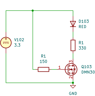
MOSFET package with series resistor on the LED to control current.

This is the basic design initially used.

MOSFET LED drive circuit

However:

  • This needs different resistors for different colours/Vf.
  • The resistors need recalculating if I supply the LEDs from 5V etc.
  • It also needs extra parts, space and layout.

Using a Prebiased npn (integrated base resistor)

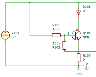
I have considered using a prebiased npn, PUMH24, instead. It has integrated bias resistors for the same size and cost.

Prebiased npn LED drive circuit

My estimated LED current range is now determined by \$\beta I_B\$. Which varies between \$ 100\times20\times10^-6 = 2mA\$ and \$200\times37\times10^-6 = 7.4mA\$. The 4x range in LED current only really has a apparent dimming effect of about half in my experience.

Current range is very similar with red, yellow, blue LEDs, current doesn't change when supply voltage changes, if base voltage comes from 3.3V MCU.

Possible concern:

  • Temp dependence, higher temp will increase \$\beta\$. Although dissipation is low, so runaway not a problem.
  • High variability between transistor drivers

Are there any other problems to consider?

\$\endgroup\$
10
  • \$\begingroup\$ Why is R103 zero? \$\endgroup\$
    – CL.
    Commented Sep 16 at 8:19
  • 1
    \$\begingroup\$ Why wouldn't you use something actually intended for the purpose at hand? e.g., assets.nexperia.com/documents/data-sheet/NCR401T.pdf \$\endgroup\$ Commented Sep 17 at 2:46
  • 1
    \$\begingroup\$ @JerryCoffin I hadn't considered and will now, although my worry is, more specific part means more risk of supply problems. Also it's double the cost of a MOSFET and resistor! \$\endgroup\$
    – EdL
    Commented Sep 17 at 7:21
  • 1
    \$\begingroup\$ @EdL: it is more, but not likely to be very significant unless you're dealing with really high volume. \$\endgroup\$ Commented Sep 17 at 7:26
  • 1
    \$\begingroup\$ @EdL You don't want boutique parts, it seems. Read this EESE answer for details. \$\endgroup\$ Commented Sep 17 at 8:58

2 Answers 2

4
\$\begingroup\$

I suspect you'll get away with it, but I don't like it. These devices are designed for saturated switching.

Minimum hFE is specified as 80, typical is more like 300 at 10~30mA (Fig 1),and typical 400 at 100°C. If we assume 600 is the maximum hFE hot, then base current hot (taking reduced Vbe into account) would be about (3.3-1.1)V/100k = 22uA and Ic would be 13.2mA. A bit more if the 3.3V bus is on the high side of tolerance, maybe almost 15mA if it's 5% high. Probably just okay.

But the resistors on the die can be 70kΩ rather than 100kΩ so it could be more than 21mA, sort-of worst case (not actual worst-case because we don't know the maximum hFE). How likely is it that all those holes in the Swiss cheese line up- that's up to you to decide.

Resistors are almost free, reputation and reliability is not. It will also let you use other makers of similar parts without a lot of worry. Or substitute parts with lower resistor values if they're out of stock on the 100kΩ ones.

\$\endgroup\$
3
\$\begingroup\$

Pre-biased transistors are designed for digital signals, so their analog characteristics are usually not very well specified. The range of β is likely to be larger than you are assuming.

You can optimize your MOSFET circuit by removing the gate resistor; small MOSFETs with a small gate capacitance (e.g., 2N7002, BSS138, DNM65D8L) can be driven directly from a microcontroller. If you want to save space, use a transistor array or an equivalent logic gate (e.g., (SN)74LVC2G06/3G06/06).

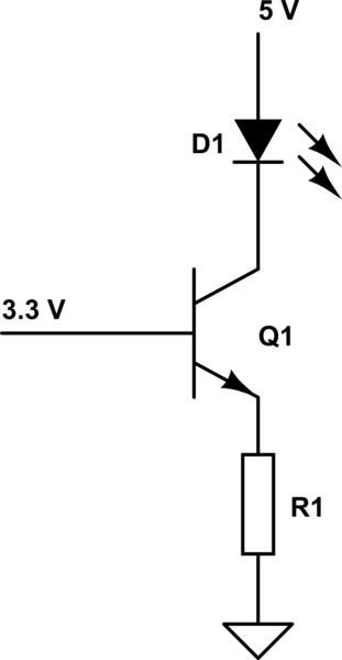
If you have a supply voltage that is higher than the MCU's supply voltage, then you can use the circuit below for a constant-current sink. (The LED current is (3.3 V − VBE) / R1. The LED's forward voltage must not be larger than 5 V − 3.3 V + VBEVCE(sat), so with these voltages, only a red LED would work.)

schematic

simulate this circuit – Schematic created using CircuitLab

\$\endgroup\$

Your Answer

By clicking “Post Your Answer”, you agree to our terms of service and acknowledge you have read our privacy policy.

Not the answer you're looking for? Browse other questions tagged or ask your own question.