If voltage at gate is ground and voltage at source is ground, then voltage at drain is VDD
No, the drain is floating assuming the threshold voltage (VTH) is a positive voltage (say 2V). I assume that you have not connected anything on the drain because your question does not mention so.
If voltage at gate is ground and voltage at source is VDD, then
voltage at drain is floating
Depends on where the substrate is connected. In case of a discrete NMOS, usually substrate is shorted to source. So, if source is VDD, substrate will also be VDD and that will pull drain to VDD-diode drop. If however, substrate is grounded, then, yes, drain is floating.
If voltage at gate is VDD and voltage at source is ground, then
voltage at drain is VDD
No, voltage is close to 0V. This is assuming that you do not have anything connected to the drain externally. Basically, in this configuration, NMOS behaves as a resistor between drain to source. So, the drain voltage will depend on the drain current and if you do not have anything connected on the drain, drain current and hence the drain voltage will be 0V.
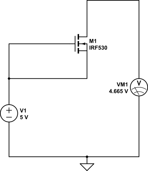
If voltage at gate is VDD and voltage at source is VDD, then voltage
at drain is ground
No, it is floating if substrate is grounded and assuming VTH is a positive number (say 2V). If substrate is shorted to source then, drain voltage is VDD - diode drop.
I suggest you try a free online simulator because what you are asking is too basic and can be easily checked by your self. For eg., for case 4, I have showed a schematic below using the tool available in this site.

simulate this circuit – Schematic created using CircuitLab

