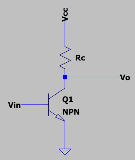
I tried to get the voltage gain (\$ A_v \$) of a Grounded Common-Emitter (GCE) Amplifier (see Fig. 1), which in many electronic textbooks is provided (sometimes without showing some algebra) and is defined as: \$ A_v = -g_mR_c\$.
It must be highlighted that this question was so far answered previously and that jonk's response shed quite a bit of light on this topic: How to derive the precise gain of an NPN common emitter amplifier without emitter degeneration? However, I would like to review it. The main reason is because I would like to understand deeply the physical-mathematical model of this circuit that a priori seems "simple". To do that, I believe that the best way is to show the math to obtain a model of this circuit configuration.
Fig. 1. Schematic of a GCE Amplifier
It is well-known that in GCE configuration, the BJT is in active mode. Therefore, we can say:
\$ I_c=I_s \cdot (e^\frac{V_{in}}{V_T}-1) \$, where \$V_T\$ is the thermal voltage.
Assuming an appropiate DC-bias point plus small-signal input voltage, we can say:
\$ V_{in}=V_{in,q}+\delta V_{in} \$
And, after some algebra, we obtain:
\$ I_c=I_s \cdot (e^\frac{V_{in,q}}{V_T}e^\frac{\delta V_{in}}{V_T}-1)=I_{c,q}+\delta I_c\$
Defining \$ I_{c,q}\$ as: \$ I_{c,q}=I_se^\frac{V_{in,q}}{V_T} \$, we obtain \$ \delta I_c\$:
\$ \delta I_c=I_{c,q}(e^\frac{\delta V_{in}}{V_T}-1)-Is \$
We know that the output voltage: \$ V_0=V_{0,q}+\delta V_0 \$ and so that: \$ \delta V_0 =-R_c \delta I_c\$
So, by sustitution:
\$ \delta V_0 =-R_c (I_{c,q}(e^\frac{\delta V_{in}}{V_T}-1)-Is)\$
Why do I think this analytical expression is correct? Well, if we assume that \$ \delta V_{in} << V_T \$, we can expand the exponential to the first term of Taylor's Series:
\$ e^\frac{\delta V_{in}}{V_T} \approx 1 + \frac{\delta V_{in}}{V_T} \$
Therefore: \$ \delta I_c = I_{c,q}\frac{\delta V_{in}}{V_T}-Is\$
Neglecting \$ I_s \$ with regard to \$I_{c,q}\frac{\delta V_{in}}{V_T}\$ we obtain:
\$ \delta I_c = I_{c,q}\frac{\delta V_{in}}{V_T} \$ and hence, the output voltage is: \$ \delta V_0 =-R_cI_{c,q}\frac{\delta V_{in}}{V_T}\$.
Remember that \$ I_{c,q}=I_se^\frac{V_{in,q}}{V_T} \$.
And, finally: \$ \delta V_0 =-R_cI_se^\frac{V_{in,q}}{V_T} \frac{\delta V_{in}}{V_T}=-g_mR_c \delta V_{in}\$ that allow us to say: \$ A_v = -g_mR_c\$.
To me, this is the process to obtain properly \$ A_v \$ and at this point, I would like to formulate my questions:
- It was shown that the famous parameter \$ \beta \$ does not appear in \$ A_v \$, or almost does not appear directly. But this is true if we use the Ebers-Moll equation for the collector current \$ I_c=I_s \cdot (e^\frac{V_{in}}{V_T}-1) \$ as done at the beginning of the process. However, one can define the base current of the BJT as \$ I_b=I_s \cdot (e^\frac{V_{in}}{V_T}-1) \$ and use \$ \beta \$ to obtain \$ I_c \$ afterwards. This would lead that \$ A_v =-\beta g_mR_c\$ by following the same process (not shown for the sake of clarity). Which one is correct? Am I missing something? The collector current equation shown here can be used only for a BJT in active mode? The \$ \beta \$ approach can be used also in active mode, where is the difference?
- There is a thing that makes me suspect that the expression for \$ A_v \$ obtained it is not entirely correct, or perhaps I am not interpreting it well. The equation obtained means to me that \$ A_v \$ is just a number since \$ R_c \$ is a number (5 k\$\Omega\$ for example) and \$ g_m \$ is evaluated at the operating point. But I think that \$ A_v\$ should varies, right? I mean, if I perform a simulation in LTSpice and computes \$ \delta V_o / \delta V_{in} \$ I would see how \$ A_v\$ varies. But in the formula I don't see that phenomena. Any help in this? What am I missing here? As an example, suppose you applied an appropiate \$ V_{be} =636 [mV] \$ to the base of the BJT plus a triangular waveform of 60 [mVpp] @1kHz. The bias point is 636 [mV], so I don't see why the voltage-gain change with the operating point. I would expect that the gain varies with the base-voltage swings.

