0
\$\begingroup\$

I realise similar questions have been asked in the past about automating capacitive touches, but I'm aiming to put this into practise with a simple circuit.

I want to be able to simulate / automate the press of a capacitive touch button on a tumble dryer. I want to do this without opening up or modifying any of the existing circuitry.

I've tested placing some aluminium foil on the button and either touching it or running a wire from it to ground (metal sink) and both work in activating it. I want to take this to the next step now and build a circuit to automate this.

I have designed what I think is the circuit to achieve this, however my electronics experience is extremely rusty going back 30 years to high school physics and some recent Googling on transistors and capacitive touch.

Before I go out and buy the components, I'm looking for some input as to whether I'm overlooking anything.

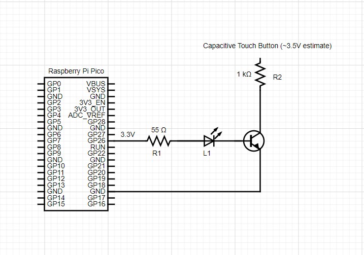
Proposed circuit diagram:

enter image description here

In the diagram, L1 is just an indicator to show me the "press", R1 is to bring the current down to about 20ma for the LED (with ~1.7V across the LED and ~0.7V across the transistor), enough to active the transistor but to keep it below the collector voltage (potential).

I've read that the potential on a capacitive touch button is between 1.8V to 5V (so I'm estimating somewhere in the middle) and R2 is just to place some load between the button and ground so there's no short to ground.

My belief is that when the GP26 is activated at 3.3V, the LED will light up and the 0.7V on the transistor will then allow the flow from the collector to emitter (i.e. ground) which would result in the button sensing a change in capacitance and activating a "press".

Am I missing anything?

\$\endgroup\$
9
  • \$\begingroup\$ L1 should probably be in a different location (and given a different reference designator; L is supposed to be for inductors!); where it is now isn't an ideal location for it. I would use a MOSFET for the transistor, personally (in which case L1 definitely would need to be moved). \$\endgroup\$
    – Hearth
    Commented Sep 30 at 15:21
  • \$\begingroup\$ Thanks @Hearth, so given the 3.3V limitation of the Pico, use it to drive the base of the NPN transistor, which in turn allows a larger voltage source (5V) to drive the MOSFET to act as a switch for the capacitive button? In which case I would consider putting the LED in parallel with the MOSFET on the 5V source with a suitable resistor. \$\endgroup\$
    – RunnerIain
    Commented Sep 30 at 17:11
  • \$\begingroup\$ @RunnerIain I think you are saying (but I'm uncertain) that the tumble dryer itself has a capacitive touch button on it that you want to control using an MCU rather than a manual touch by hand and that you've done a little bit of testing, finding that "grounding" a certain point appears to work. And you want to make a circuit for the MCU that both turns on an LED and also activates this switch? And you will be sharing the MCU ground with the dryer's ground somehow? \$\endgroup\$ Commented Sep 30 at 17:54
  • \$\begingroup\$ @periblepsis, the tumble drier "start / stop" button is capacitive touch. I've found that by taping a piece of foil onto the button and grounding the foil, it activates the button. I'm trying to simulate that electronically by creating a circuit that attaches that piece of foil to ground programmatically, in this case the ground would be the one on the Raspberry Pi Nano (GND pin), or some other external ground which suits the purpose. I won't interact with any of the electronics inside the tumble dryer itself, the only direct interaction is placing the foil over the capacitive button. \$\endgroup\$
    – RunnerIain
    Commented Sep 30 at 18:40
  • \$\begingroup\$ @RunnerIain I think I may see better. Is it that your testing only involves placing a tiny piece of foil and then connecting that foil to the earth ground of the dryer? \$\endgroup\$ Commented Sep 30 at 18:46

2 Answers 2

0
\$\begingroup\$

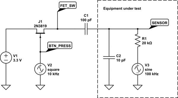
You can turn on and off a capacitive sensor load using a JFET as switch. The advantage compared to a MOSFET is, that there is no body diode remaining connected to the capacitor during the off state and the output capacitance is pretty low.

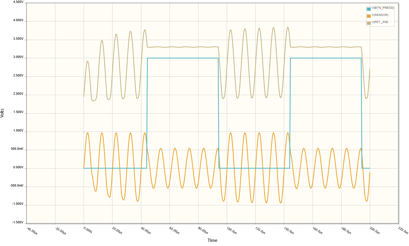
If BTN_PRESS is high (close to 3.3 V, blue track) J1 is conducting and so your touch foil C1 has an AC GND connection. The amplitude at FET_SW is very low in this phase.

The amplitude the sensor sees, is reduced and the phase is shifted, so a touch will be recognized.

If BTN_PRESS is low, J1 is turned off and this disconnects the foil (C1) from GND. FET_SW shows the coupled sensor signal amplitude, because this point has a high impedance now.

This, however, does not work properly if GND of the MCU circuit has no connection to the EUT GND.

The cutoff voltage of the JFET (e.g. MMBF5484) must be below the MCU supply voltage to turn it fully off.

schematic

simulate this circuit – Schematic created using CircuitLab

TestCycleSignals

\$\endgroup\$
1
  • \$\begingroup\$ Thanks @Jens, this is a bit more complicated than I had been expecting and I'll need to give it some thought and get my head round it! Appreciate you taking the time to outline this I detail! \$\endgroup\$
    – RunnerIain
    Commented Sep 30 at 19:36
0
\$\begingroup\$

A NPN will work better than a mosfet for this because most FETs you can buy will have too much D-S and D-G capacitance even when off.

The NPN needs a pull-up (when off). Change your R2 to 1 MΩ; tie the top to V3v3_out and the junction of the R and collector to the capacitive button.

Now when the npn turns on (and saturates) it will appear to have a large capacitance at its collector.

\$\endgroup\$
1
  • \$\begingroup\$ Thanks @jp314. I wasn't aware of the requirement for the pull up, I'll modify accordingly. \$\endgroup\$
    – RunnerIain
    Commented Oct 3 at 11:36

Your Answer

By clicking “Post Your Answer”, you agree to our terms of service and acknowledge you have read our privacy policy.

Not the answer you're looking for? Browse other questions tagged or ask your own question.