0
\$\begingroup\$

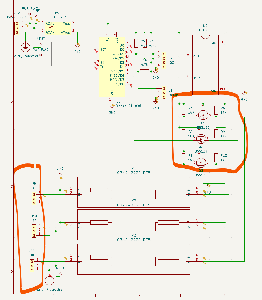
I use BSS138 to shift the output voltage of ESP8266 up to 5 V. Then the output is sent to the input pins of G3MB-202P.

When I turn on D4/D7/D8 pin, voltage appears on screw connectors, but it barely moves 40 W fan. Additionally, it generates a buzzing sound. I suppose it is related to the fact that G3MB-202P turns off on zero and level shifter does not provide constant “flat” current to the input. Unfortunately, I don't have an oscilloscope to check it.

My multimeter says that voltage drop on G3MB-202P is 1.2 V when D4/D7/D8 is low and 2.6 V when it is high.

I'm additionally surprised because I have (almost) the same circuit built on breadboard modules, and it works — 40 W water pumps are working without giving strange sounds.

enter image description here

Edit BSS138 circuit is a copy of this module schematic is available under documents ⇾ schematic link. I use this module in my prototype and it works.

My prototype has modules based on G3MB-202P which includes some additional elements like screw terminals LED diode and resistors. I don't have schemas, but I doubt if they affect the circuit.

I'm newbie in SMD soldering, so some elements may be not connected perfectly, but I test my circuit for resistance with multimeter.

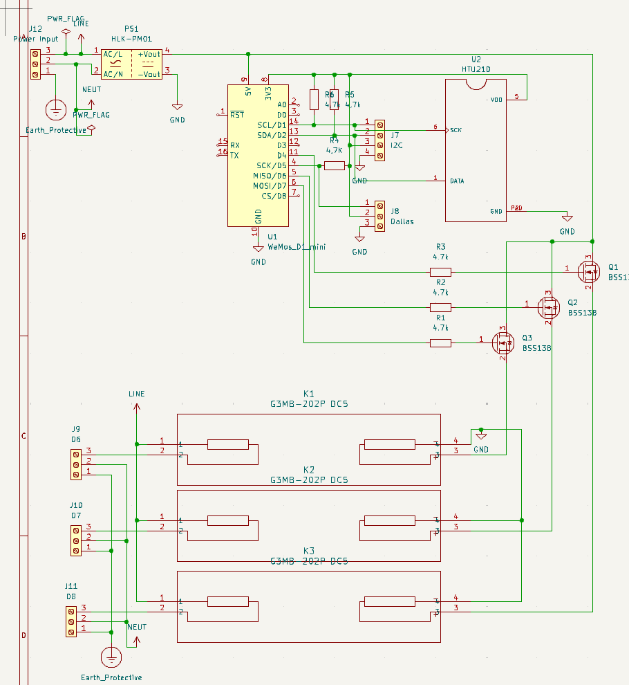
After talk witj @winny I've updated my circuit to use transistor as a regular DC SSR enter image description here
\$\endgroup\$
9
  • \$\begingroup\$ that "level shifter" seems off to me, like it would divide the voltage instead of switch it. Are you seeing 5v across the input of the SSR when it's on? And wouldn't the FET's body diode feed current regardless of the gate voltage? Why not just pull the SSR input high with a 10k, and ground it with the fet when the gpio is on? \$\endgroup\$
    – dandavis
    Commented Oct 1 at 8:17
  • \$\begingroup\$ Are you trying to supply you load through your ESP? \$\endgroup\$
    – winny
    Commented Oct 1 at 10:52
  • \$\begingroup\$ @winny No. WEMOS D1 (and NodeMCU) has 5V pin. You can use it to power 5V devices when powered from USB or you can power ESP with it (board has built-in voltage converter). G3MB-202P requires 5V drive. \$\endgroup\$
    – szogun1987
    Commented Oct 1 at 15:53
  • \$\begingroup\$ So though what does the current though Q1-3 come from, and more particularly, though in your schematic? \$\endgroup\$
    – winny
    Commented Oct 1 at 18:14
  • \$\begingroup\$ @winny As far as I understand when D4/7/8 is low Q1/2/3 are open and voltage on drain drops significantly as current from 5V flows in 2 directions (some via K1-3 and some via Q1-3 to D4/7/8 and via R1-3 to 3.3V. When D4/7/8 is high Q1-3 are closed and all current flows via K1-K3, but in practice is not. BTW this is bi-directional logic converter, I don't need this feature I just copy sub-circuit I used in working prototype (check link in question). \$\endgroup\$
    – szogun1987
    Commented Oct 2 at 7:39

0

Your Answer

By clicking “Post Your Answer”, you agree to our terms of service and acknowledge you have read our privacy policy.