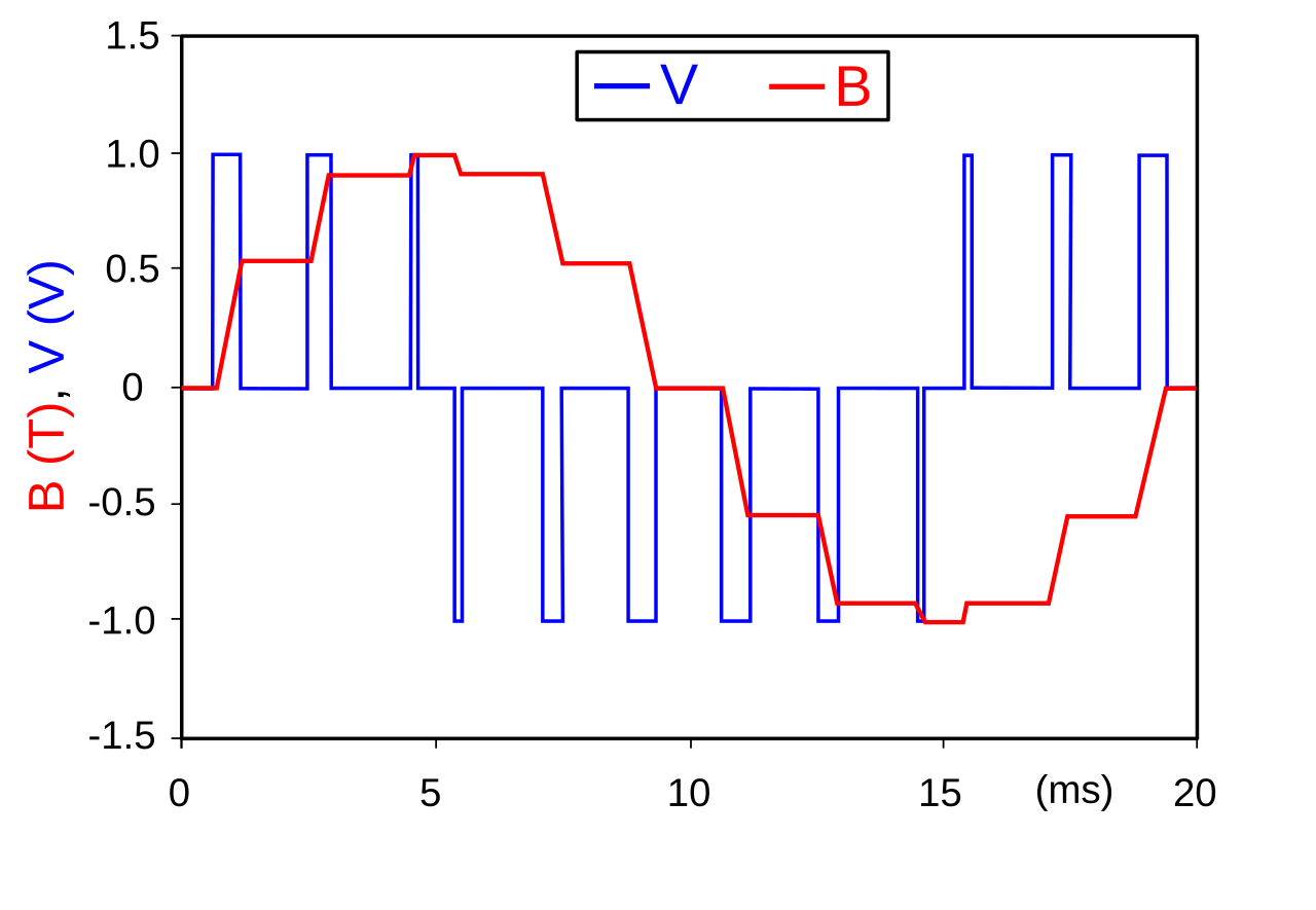
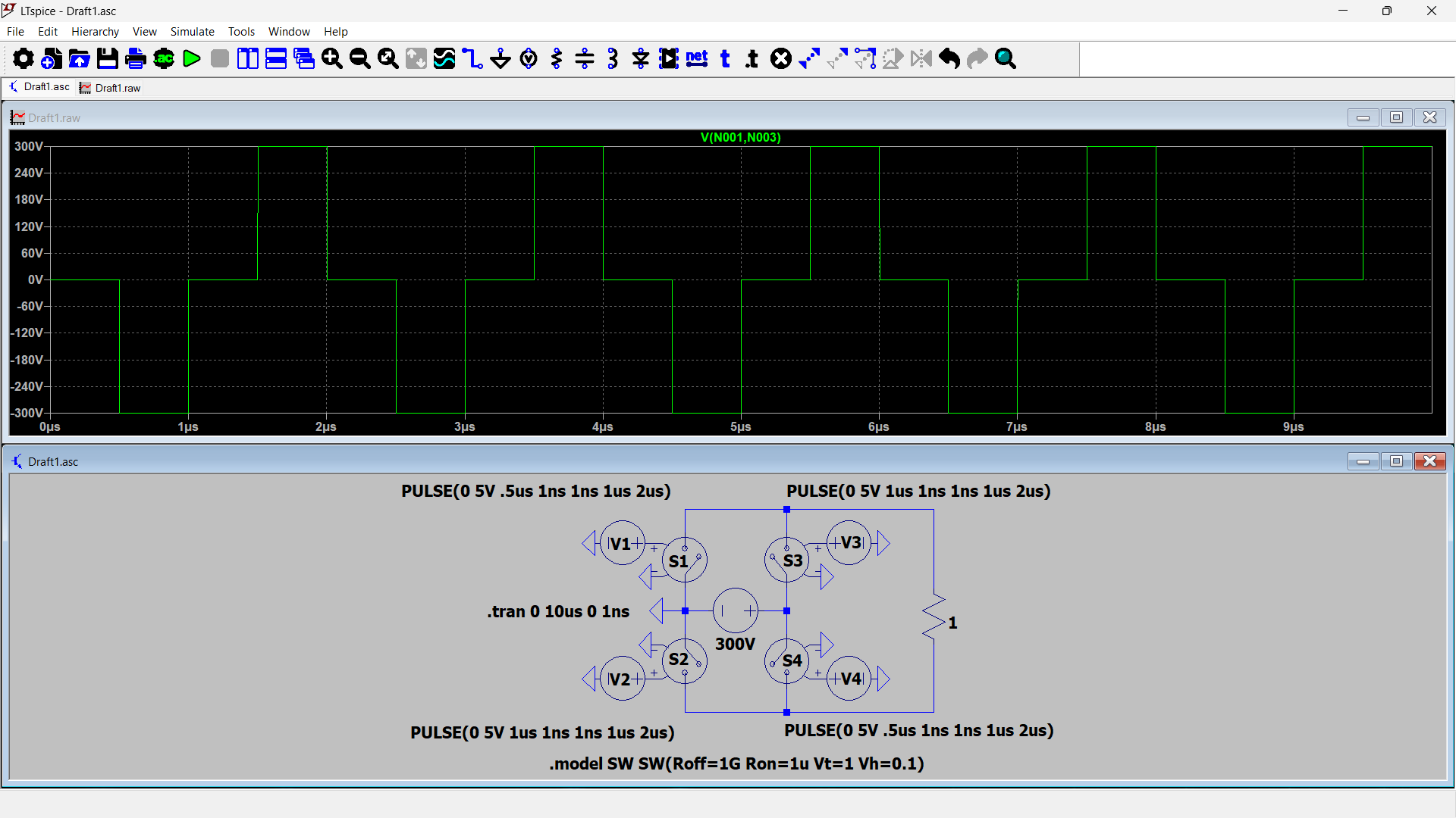
 How does one go about simulating a PWM sine wave in LTspice? So far, my only idea is to add more voltage sources in parallel as the gate drivers of the H-bridge switches, but it seems too hacky and messy.
-
1\$\begingroup\$ Have you tried the behavioral voltage source BV or just supply a PWL file to a regular voltage source? \$\endgroup\$– winnyCommented Oct 2 at 18:06
-
\$\begingroup\$ Thanks! Will look into PWL files and end up writing a python script to generate them. It would be cool if one could take the output waveform and feed back into some script that would be running on a microcontroller, but I doubt LT spice supports that and even if it does, it is likely very slow... \$\endgroup\$– beardeadclownCommented Oct 2 at 18:16
-
1\$\begingroup\$ ltspice can emit WAV files, you can probably convert that to something your compiler understands using "sox" and a script \$\endgroup\$– Jasen Слава УкраїніCommented Oct 3 at 0:11
2 Answers
You could use a comparator to compare some arbitrary input waveform,with a much higher frequency sawtooth:
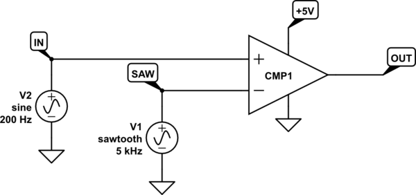
simulate this circuit – Schematic created using CircuitLab
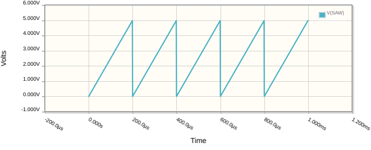
The sawtooth \$V_{SAW}\$ looks like this:
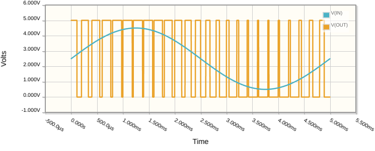
\$V_{IN}\$ is the signal to be converted to PWM. A sinusoidal \$V_{IN}\$ and the corresponding PWM output \$V_{OUT}\$ look like this:
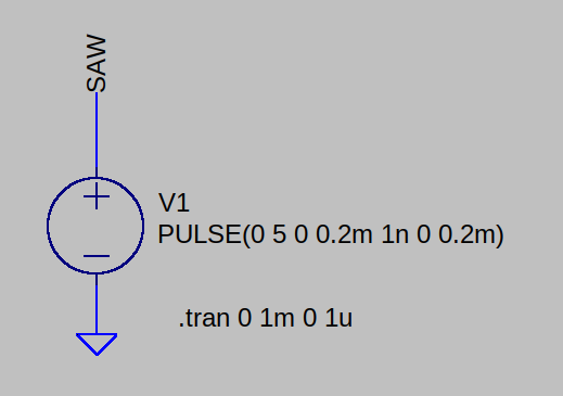
In LTSpice you can create a 5V, 5kHz sawtooth using a PULSE directive attached to a voltage source:
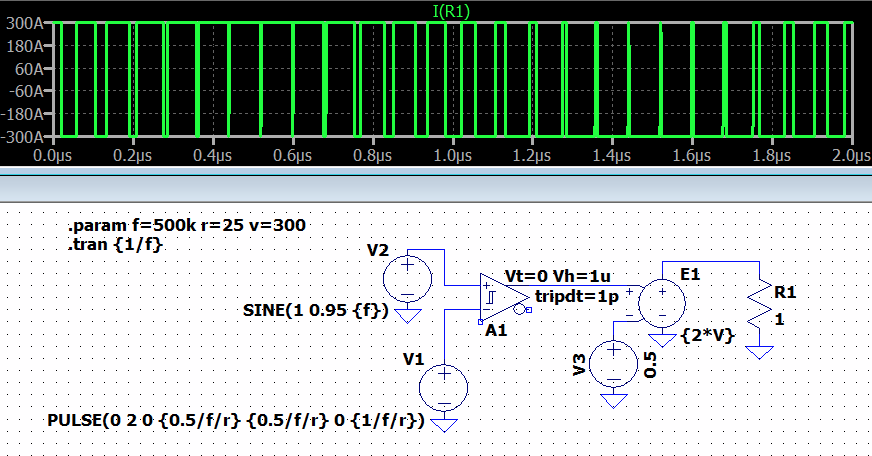
In LTspice, perhaps an adaptation of something like this:
Above, v is the output voltage you want. f is the sinusoidal frequency. And r is an integer to use for oversampling of f. I set it to 25, but feel free to set it to 100, or something else. There's some flexibility here.
The Schmitt parameters may need adjustment depending on the speed of things. Here, I decided to make them constants. But they may need, instead, to be a function of the chosen frequency, like other items in the schematic already are. I just didn't want to spend the extra time on fine-tuning that. Just wanted to get across an approach with specific devices shown.

