The problem
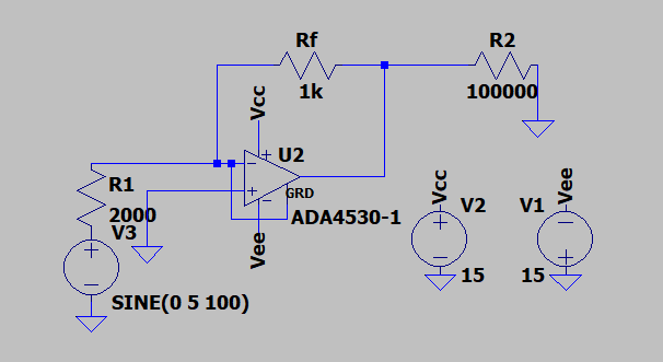
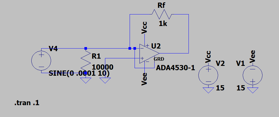
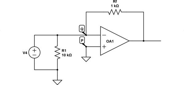
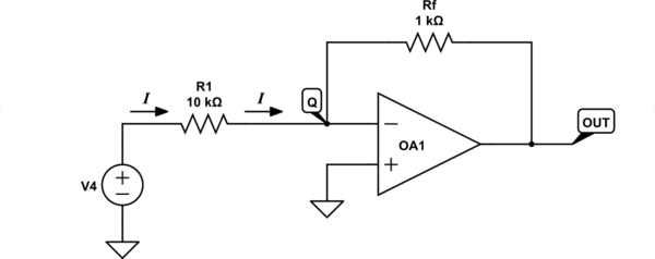
In the simplified example, I have a component (here a 10000 ohm resistor) which I am biasing and trying to measure the current through.
Your task seems to be reduced to measuring the resistance of the DUT (Device Under Test), or simply put, to create an ohmmeter. Another possibility is that you are asked to measure the IV curve of the DUT, that is, to create a curve tracer. I am not sure which one it is, so I will check out both options.
Basic idea
The relationship between voltage, current, and resistance is given by Ohm's law (I = V/I or V = I.R).
If your task is to make an "ohmmeter", resistance is the input variable. Depending on which variable is the output, we have two ways to solve the problem:
Keep the voltage constant and measure the current as a function of the resistance (Iout = Vref/Rin).
Keep the current constant and measure the voltage as a function of the resistance (Vout = Iref.Rin).
If you have to make a curve tracer, resistance is a parameter. Depending on which variable is the input and which the output, we have two more ways to solve the problem:
Keep the resistance constant and measure the current as a function of the voltage (Iout = Vin/Rdut).
Keep the resistance constant and measure the voltage as a function of the current (Vout = Iin.Rdut).
All these conversions can be implemented by an inverting amplifier topology. At its core, this configuration comprises two devices in series (cascaded): a voltage/resistance-to-current converter (R1) followed by a current/resistance-to-voltage converter (R2). The operational amplifier serves the crucial role of establishing ideal operating conditions, specifically a virtual ground at the junction between the two converters.
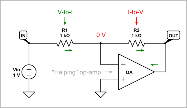
simulate this circuit – Schematic created using CircuitLab
The circuit solutions that implement these ideas are simple and straightforward, but there is a lot of underlying philosophy worth exploring. The best way to do this is to build and examine them step by step using simulations.
Resistance-to-current conversion
Passive resistance-to-current converter
If I put the test resistor in series with the voltage supply it seems to work ok.
This is essentially the simplest 19th-century Ohmic circuit, where we apply a constant voltage Vref across a variable resistor Rin and measure the current Iout flowing through it. Metaphorically speaking, in this way the resistance is as if "converted" into current.
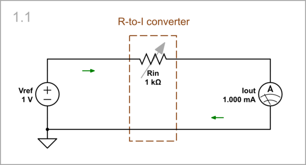
simulate this circuit
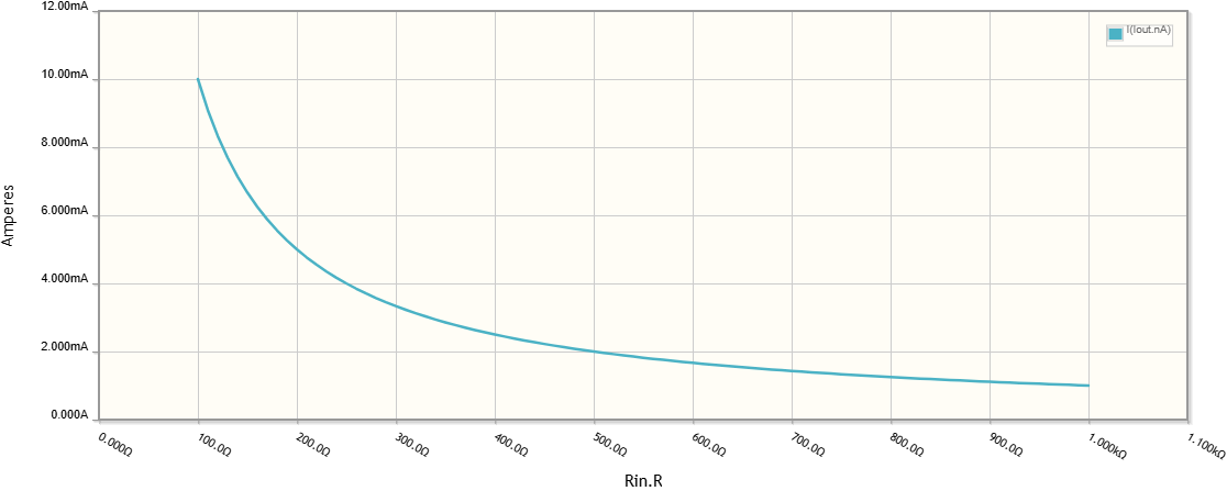
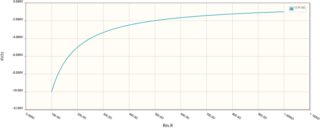
By DC sweeping the IV characteristic of this converter (resistor) through a CircuitLab DC Sweep simulation, we see that it is highly nonlinear (hyperbolic), which is undesirable.
Adding an output current-to-voltage converter
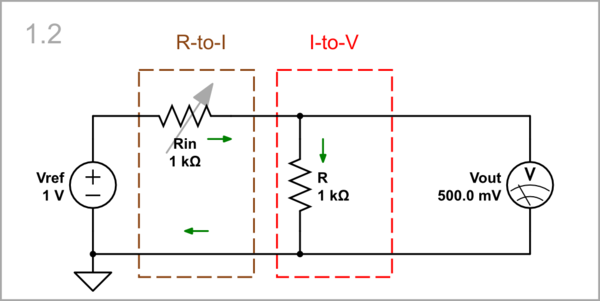
However, we want voltage, not current. That is why, we connect another resistor R in series and take the voltage drop across it as an output voltage Vout.
simulate this circuit
Now, another problem arises - the voltage drop across the resistor R is subtracted from the input voltage (resistance R is added to Rin) and the current, accordingly the output voltage, decreases.
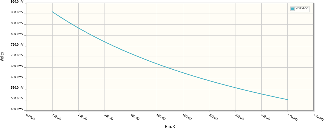
Adding a compensating voltage source...
But we are inventive enough to find a remedy - we connect another but negative voltage source Vout in series so that its voltage compensates for the VR drop (travelling the loop, it is added to the input voltage and thus it supports the input source). The result is amazing - the old output voltage becomes zero and the current depends only on Vref and Rin. We use the compensating voltage as a new (grounded and inverted) output.
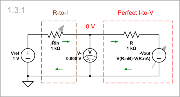
simulate this circuit
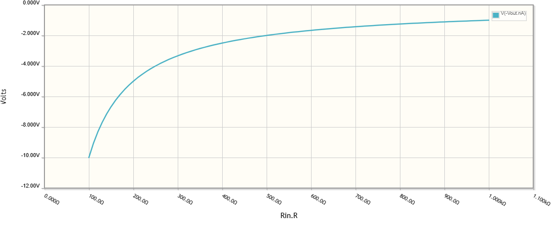
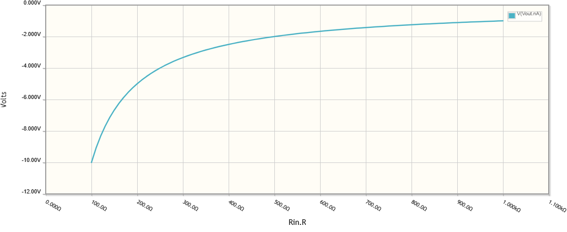
The DC sweep graph is a mirror copy of that below Schematic 1.1 above.
... or equivalent negative resistance
Figuratively speaking, the compensating source plays the role of a negative resistor with resistance -R which annihilates R.
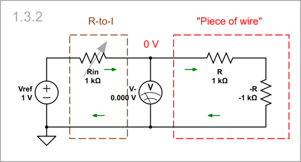
simulate this circuit
Equivalent circuit
The result is the same - a "piece of wire".
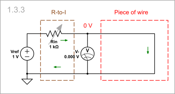
simulate this circuit
Op-amp implementation
In your circuit, an op-amp output voltage plays the role of the compensating voltage (the circuit is actually an inverting amplifier).
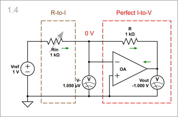
simulate this circuit
Resistance-to-voltage conversion
Passive resistance-to-voltage converter
With the same success, we can pass a constant current Iref through the variable resistor Rin and measure the voltage Vout across it. Now we can say that the resistance is "converted" into voltage.
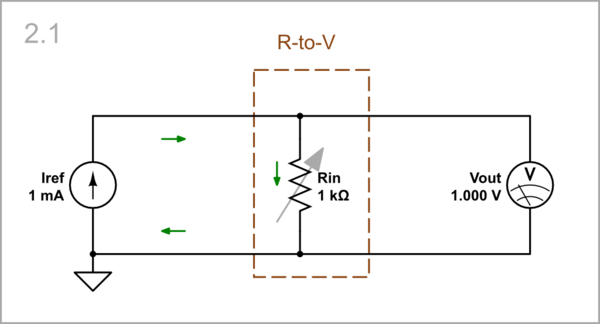
simulate this circuit
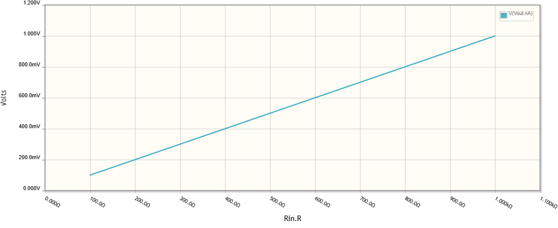
A pleasant surprise is that the voltage depends linearly on the resistance.
Adding an input voltage-to-current converter
We can make the reference current source with a reference voltage source Vref and a constant resistor R.
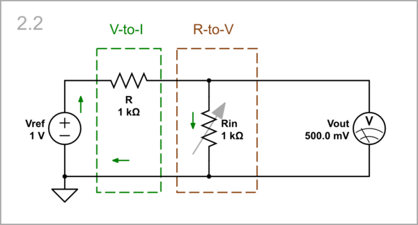
simulate this circuit
However, the variable resistor Rin disturbs the operation of this simple current source as R in Schematic 1.2 above.
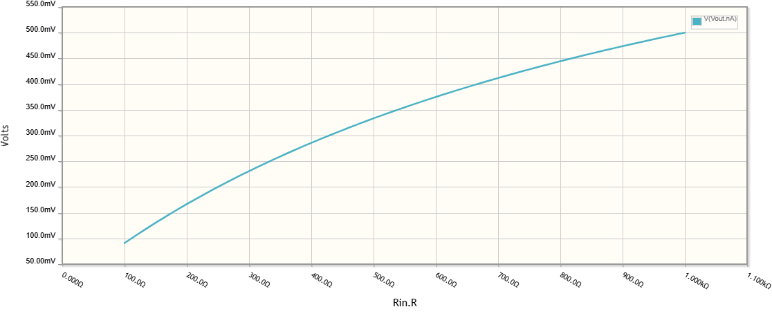
Adding a compensating voltage source...
The remedy is the same - we connect another voltage source Vout in series to Rin so that its voltage compensates for the VRin drop. The result is the same - the old output voltage becomes zero and the current depends only on Vref and R. The compensating voltage serves as a new (grounded and inverted) output.
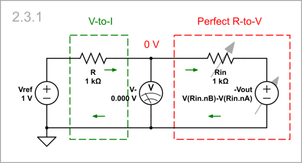
simulate this circuit
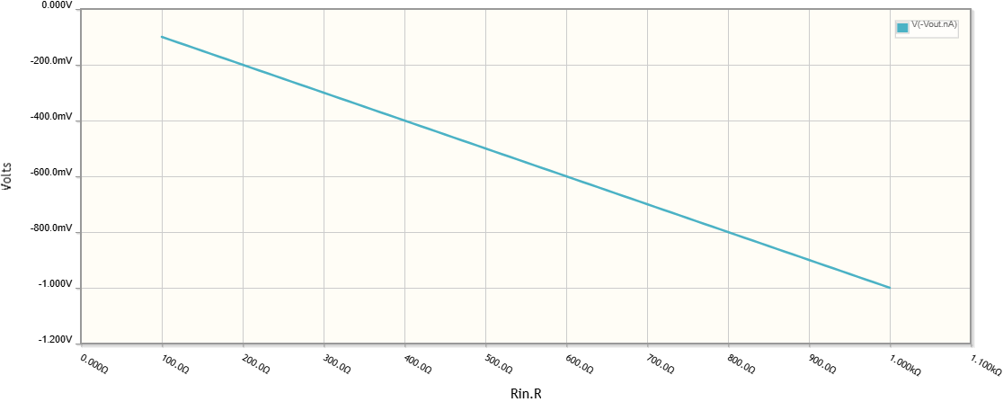
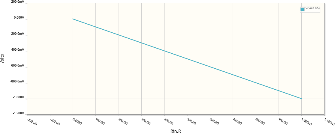
The output voltage is linear and inverted.
Equivalent circuit
As a result, the right part of the circuit behaves as a short connection.
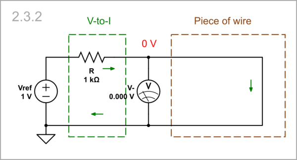
simulate this circuit
Op-amp implementation
It is the same as Schematic 1.4 but with swapped resistors (the circuit is actually an inverting amplifier). A disadvantage is that Rin is not grounded.
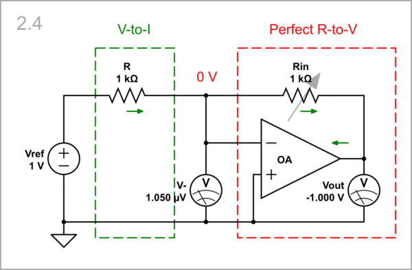
simulate this circuit
The output voltage is linear and inverted.
Voltage-to-current conversion
If your task us to measure the IV curve of a DUT, then you have to vary the voltage across or the current through it and to measure the current through or the voltage across it.
Linear V-to-I DUT
If the DUT is linear (resistor), it can replace either R1 or R2 in the inverting amplifier configuration. Let's first put it in for R1 here.
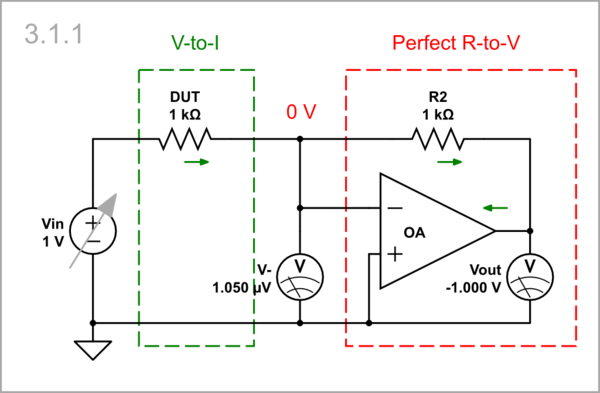
simulate this circuit
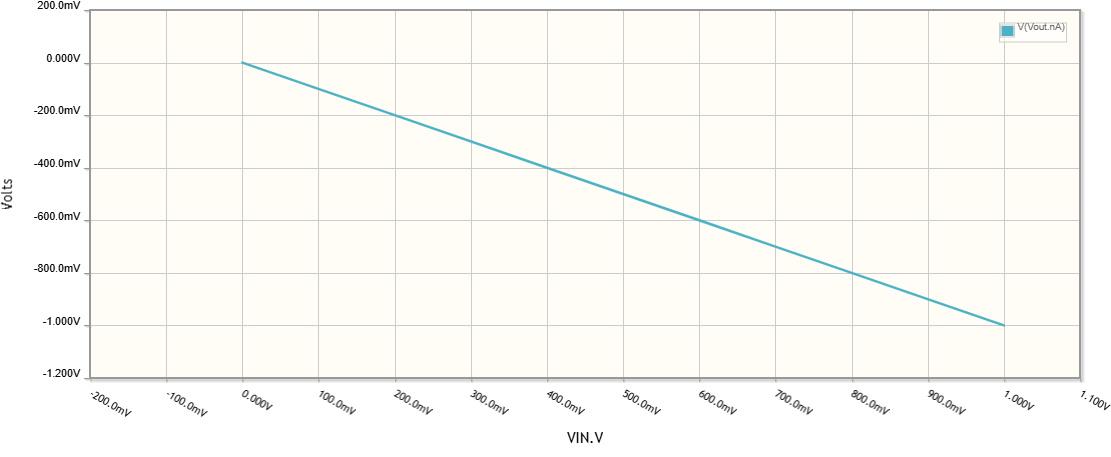
The IV curve is linear (Ohm's law).
Non-linear V-to-I DUT
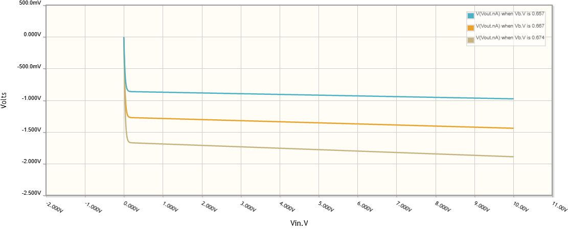
However, if the DUT is nonlinear, its placement depends on the shape of its I-V curve. If it is current stabilizing, then it should replace R1; otherwise, a conflict between two current sources will occur. As an example, let's examine the output characteristic of a bipolar transistor or a family of characteristics.
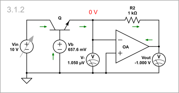
simulate this circuit
As you can see, the partial curves have an almost horizontal region.
Current-to-voltage conversion
Linear I-to-V DUT
If the DUT is linear (resistor), it can also replace R2 in the inverting amplifier configuration.
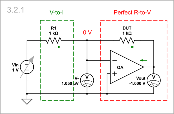
simulate this circuit
The IV curve is the same as the one under Schematic 3.1.1.

Non-linear I-to-V DUT
If the DUT is nonlinear voltage stabilizing, then it should replace R2; otherwise, a conflict between two voltage sources will occur. As an example, let's examine the IV curve of a diode.
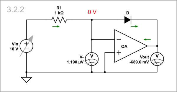
simulate this circuit
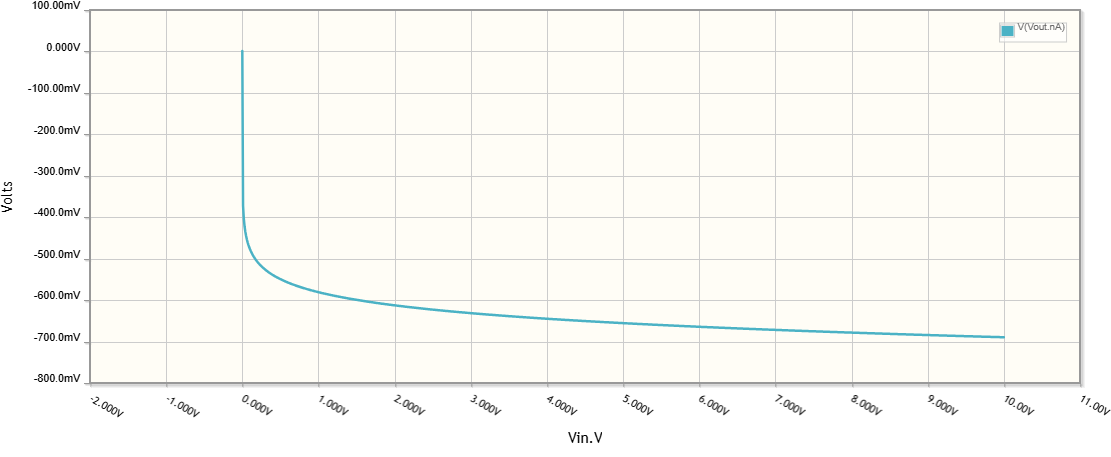
Now the curve has an almost vertical part.
