2
\$\begingroup\$

I'm trying to design a PCB that is pluggable into another PCB, each one being inside separate plastic enclosures. I'm having a hard time finding a component that I can solder on a PCB and that can make the connection to the other PCB. The plugs should be able to handle mains voltage and around 10 A of current, that's why they need to be inside the enclosure, in order to be safe to operate.

I can only find components that are made to plug two PCBs together but can only be used with both PCBs inside the same enclosure due to having very small pins.

A possibility would be power outlet female connectors and plugs, but that are solderable to a PCB, like the ones they use in Smart plugs, as can be seen on some Youtube Smart Plug Teardown videos such as this one.

It doesn't necessarily need to be pluggable into a power outlet, all I need are two connectors, one female and another male that are pluggable into each other that I can have soldered into a PCB. I tried searching for pluggable terminals but didn't have much luck.

So I would like if someone could give me a search keyword or a product link so that I can find these components, ideally in the JLCPCB's Parts Library, which is the PCB manufacturer I'm going to be using.

\$\endgroup\$
14
  • 2
    \$\begingroup\$ Is there a reason you don't want to use a panel-mount connector and wire it to the board? A mezzanine connector (if one exists in your size) would be difficult to mount in such a way that you would have acceptable ingress protection and will transfer mating forces directly to the board. \$\endgroup\$
    – vir
    Commented Oct 12 at 17:02
  • \$\begingroup\$ @vir The reason not to use a panel mount is make the assembly easier, just screwing the board to the enclosure instead of having to connect wires from the panel-mount connector to the board. But that could be a plan B. \$\endgroup\$
    – Ohmnivore
    Commented Oct 12 at 17:37
  • 2
    \$\begingroup\$ My recommendation is still to use panel-mount but if you want to continue with this you should also edit the original question to include what other signals are being transferred, whether both sides need to be touch-safe for mains voltage, the distance between the boards, the distance between the board and the enclosure, and any other constraints or requirements. A board-mount D-sub style connector with power pins could work. \$\endgroup\$
    – vir
    Commented Oct 12 at 17:41
  • \$\begingroup\$ @vir I need 3 pins touch-safe, and another one that would be better to be touch-safe but not strictly necessary. But I think it is easier to make them all pluggable in the same mechanism (i.e. touch-safe) \$\endgroup\$
    – Ohmnivore
    Commented Oct 12 at 17:52
  • \$\begingroup\$ Why don’t you simply use 4 mm (security) banana test plug/socket? You could easily find numerous types. \$\endgroup\$
    – user317139
    Commented Oct 13 at 0:14

4 Answers 4

2
\$\begingroup\$

Here is a method

enter image description here

\$\endgroup\$
1
  • \$\begingroup\$ Firstly, many thanks for your detailed answer, one of the most detailed so far indeed. The problem with those connectors is that one board could be live at mains voltage at the time of connection. Since the connector requires a huge hole on the enclosure, I have some concerns regarding it. Because due to the size of the Receptacles holes, it seems easy to get into contact with them. I tried Digikey but could not filter for 600V+ and by searching for "600V" I could not find any there. The quick connect terminals suggested by Voltage Spike seem to allow for somaller holes in the enclosure. \$\endgroup\$
    – Ohmnivore
    Commented Oct 16 at 19:35
1
+50
\$\begingroup\$

Probably the best thing is something like a terminal

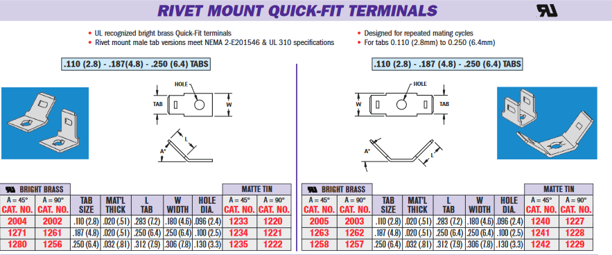
Look at quick connect terminals, you can get them with SMT mounts or screw mounts. There are lots of options, here is some examples:

For the male side (there are different angles) enter image description here
Source: https://www.keyelco.com/userAssets/file/M65p60.pdf

This one is a rivet, but you should also be able to put a pem nut into your pcb or a screw an nut to hold it in. There are solder-able versions of these, but I'd prefer a screw for strain relief.

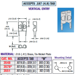
Female side if you need right angle PCBs:
enter image description here
Source: https://www.keyelco.com/product.cfm/Horizontal-Entry/3571/product_id/682

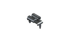
Female vertical. enter image description here
https://www.keyelco.com/userAssets/file/M65p61.pdf

They are UL rated so you shouldn't have trouble there and I think they are 10A but that isn't apparent if that applies to that connector on the sheet.

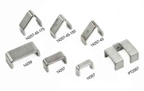
Another option if you need high current is a pcb shunts, but these are probably too bulky for your application, but I wanted to show what exists.

enter image description here https://lugsdirect.com/PCB-Shunts-and-Jumpers.html

Many people just end up machining something out of copper or sheet metal copper plate with two holes and then soldering or using a fastener to mount them to a PCB.

\$\endgroup\$
5
  • \$\begingroup\$ Many thanks for the detailed answer, considering both male and female (or Receptacle and header) sides, with product references. In fact, using quick connect terminals already came to my mind. My problem was, in the case of through-hole terminals, I was afraid they might not stood completely vertical and, therefore, not align properly to connect both board, given that I want the enclosure hole to be as tight as possible, for safety, since one side could be live at mains voltage. But those SMD, due to having a flat board mounting surface, seem a lot more promising. \$\endgroup\$
    – Ohmnivore
    Commented Oct 16 at 19:53
  • \$\begingroup\$ You may need something custom machined. You can get sheet metal cut at many machining places (oshcut.com/capabilities) and bent. All you would need is a simple bracket with two holes for fastners, which would be easily drawable in a dxf. You could also probably make a solderable one also, but that would take some experimentation. If you like the answer (and other answers) be sure to use the voting system. Also make sure you pick your favorite answer before the deadline so the rep doesn't get lost. \$\endgroup\$
    – Voltage Spike
    Commented Oct 16 at 20:32
  • \$\begingroup\$ You suggest something custom machined to replace the Quick Connect terminals you referred above? Don't you think the SMD quick connect terminals would align properly? \$\endgroup\$
    – Ohmnivore
    Commented Oct 17 at 16:15
  • \$\begingroup\$ I've upvoted the best answers. Yes, I'll award the reputation, I'm just waiting to get as many answers as possible. \$\endgroup\$
    – Ohmnivore
    Commented Oct 17 at 16:16
  • \$\begingroup\$ Thanks for participating! \$\endgroup\$
    – Voltage Spike
    Commented Oct 17 at 16:31
0
\$\begingroup\$

I would probably use something like the below. If you don't need any cable whatsoever between the two you could shorten the wires and mount appropriately. As others have mentioned I would be careful not to stress terminations or the board.

https://www.digikey.com/en/products/detail/schurter-inc/6182-0033/1787799 https://www.schurter.com/en/datasheet/9009

\$\endgroup\$
0
\$\begingroup\$

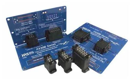
Hirose -> Category -> Power

You'll find options here.

\$\endgroup\$

Your Answer

By clicking “Post Your Answer”, you agree to our terms of service and acknowledge you have read our privacy policy.

Not the answer you're looking for? Browse other questions tagged or ask your own question.