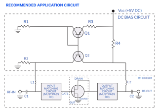
I am looking into the datasheet of a SAV-541+ E-PHEMT RF transistor, and looking at the recommended biasing circuit, im not sure how the drain current is determined.
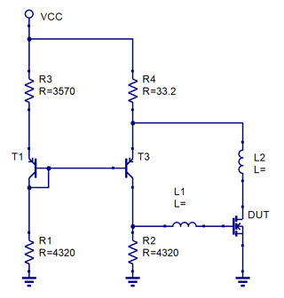
Above is the picture from the datasheet of the circuit. Below i have redrawn it, as i believe it makes the current mirror drawn more typical:
How do i calculate the drain current in this circuit, and more importantly, be able to calculate other resistor values for different current and drain voltages? It would make more sense to me, if the Drain-source of the device would be connected where R2 is. Of course this would leave the gate voltage unbiased.
For the values in the schematic, the drain current should be around 60 mA with a 3 V at the drain. VCC is 5 V. For this E-PHEMT device, \$V_{GS}\$ is around 0.5V for this drain current.
Also i wonder how tolerant this circuit is on varying gate threshold voltage \$V_{th}\$.


