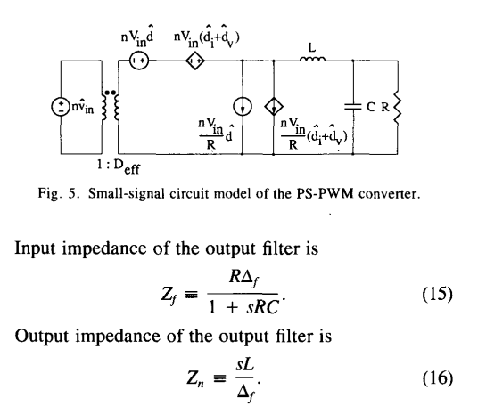
I was trying to construct small signal analysis for phase shift full bridge converter. Below is the point that I reach.
According to the document, the transfer function of the output filter is given as in the 2'nd picture. I can derive it, it is easy. It is just a transfer function of LC filter with the Rload.
My question is as you can see in the 1'st picture, document calculated the input impedance and output impedance of the output filter.I didn't understand anything where these two equation come from. How can I derive it? and where does these two equation come from?
Secondly, what is this Δf? don't we generally equate the transfer function to the Vout/Vin?
 Source: https://www.researchgate.net/publication/3279135_Small-signal_analysis_of_the_phase-shifted_PWM_converter/link/545ce4bc0cf2c1a63bfa58b2/download?_tp=eyJjb250ZXh0Ijp7InBhZ2UiOiJwdWJsaWNhdGlvbiIsInByZXZpb3VzUGFnZSI6bnVsbH19
 Source: https://www.researchgate.net/publication/3279135_Small-signal_analysis_of_the_phase-shifted_PWM_converter/link/545ce4bc0cf2c1a63bfa58b2/download?_tp=eyJjb250ZXh0Ijp7InBhZ2UiOiJwdWJsaWNhdGlvbiIsInByZXZpb3VzUGFnZSI6bnVsbH19
