7
\$\begingroup\$

I have a question regarding the use of 0-ohm resistors in electronic circuits. While I know they are commonly used as jumpers to connect different parts of a circuit, I’m curious if there are other applications or benefits to using them.

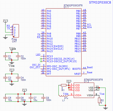
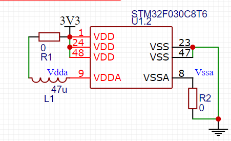
For example in this MCU circuit there is a 0-ohm resistor in both VDD and VSSA. Could they have other applications in this circuit? If so, is it necessary to use them in my circuit too?

enter image description here

This is full schematic I found in the Internet, if you need

enter image description here

\$\endgroup\$
1
  • \$\begingroup\$ Saeed - Hi, Where did the images come from? To comply with the site rule on referencing, details of the original source of copied / adapted material must be provided by you, next to each copied / adapted item. If the original source is online & public, please edit the question & add the webpage/PDF/video name & its link (URL) (e.g. website name + webpage title + its URL). If the source is offline (e.g. printed book or private intranet) then edit the question & add full source details e.g. title, author, page, publisher, edition. TY \$\endgroup\$
    – SamGibson
    Commented Oct 17 at 10:58

3 Answers 3

5
\$\begingroup\$

For example in this MCU circuit there is two 0-ohm resistor in both VDD and VSSA.

They are there to disconnect the analog supply for testing/evaluation/etc. Likely reasons include:

  • It's a leftover from revision 0 of the board that was needed in the R&D phase.

  • It helps troubleshooting needed on the production line, usually during the initial stages of the product's life cycle.

  • It helps troubleshooting field failures - whether due to issues with the design, or abuse in the field.

\$\endgroup\$
6
  • \$\begingroup\$ I don't see why you would like to disconnect the analog supply for any reason. It would exceed the absolute maximum rating for that MCU and it would damage. Same also for VSSA. Of course we are not given the full schematics. The 47 uH inductor between supplies sounds like trouble too, so it might just be a poor circuit example anyway. \$\endgroup\$
    – Justme
    Commented Oct 17 at 10:28
  • \$\begingroup\$ @Justme about Inductor, I supposed that is ferrite bead, am I mistaken? \$\endgroup\$
    – Saeed
    Commented Oct 17 at 10:43
  • 1
    \$\begingroup\$ @Saeed You are mistaken. It is not a ferrite bead as you are unlikely to have a 47uH ferrite bead and ferrite beads are generally not rated in inductance anyway, but as impedance. It must be an inductor because it reads 47 uH. \$\endgroup\$
    – Justme
    Commented Oct 17 at 10:48
  • \$\begingroup\$ is it a good idea to replace a ferrite bead instead of that inductor? \$\endgroup\$
    – Saeed
    Commented Oct 17 at 10:52
  • 1
    \$\begingroup\$ @Justme It may well be that whoever knew about those potential uses for a jumper misapplied them. I have seen the jumpers used for all those purposes in the circuits other people designed. Seeing undamped inductors in some power supply circuits gives me literal shivers. \$\endgroup\$ Commented Oct 17 at 10:54
4
\$\begingroup\$

It really depends what you mean when you think them as jumpers.

There are electrical uses and physical uses.

For example, if you are making a one sided PCB and need to cross over some tracks with some method, a 0R will mechanically do that without interfering much with the signal.

In the example you post, there might be electrical reasons based on what the designer was thinking. The 0R resistors can be replaced with other value resistances if necessary, or replaced with ferrite beads if needed. So the 0R can simply be a placeholder for something else and enable you to more easily test or verify or modify the circuit as needed, so you don't have to order a new board immediately if you plan ahead.

For example the VDDA resistor could be turned into a ferrite bead.

It can be impossible to say based on that narrow screeshot if there are other reasons for the resistors.

They may also useful for using them in sectioning the PCB design, and used as a link between analog and digital ground reference planes.

You may find these tricks useful in your design, or you might not. Certainly a design does not require them, you can do without.

However that circuit you show may be a poor example anyway. Usually you would not see a 47 uH inductor between VDD and VDDA supplies of the MCU. Of course a lot of the details like bypass caps are missing from the screenshot.

\$\endgroup\$
3
  • 1
    \$\begingroup\$ @Saeed unless you have nothing else to ask about the answer, do not just put "thank you" under each answer. \$\endgroup\$
    – Justme
    Commented Oct 17 at 10:38
  • 1
    \$\begingroup\$ Based on our culture, we appreciate if someone do us a favor. \$\endgroup\$
    – Saeed
    Commented Oct 17 at 10:49
  • 5
    \$\begingroup\$ @Saeed that is not the purpose of the comment section in EE.SE, leaving compliments is under the list of when not to comment. If you like an answer, a better way to show gratitude is to upvote it. \$\endgroup\$
    – Justme
    Commented Oct 17 at 10:56
2
\$\begingroup\$

They can sometimes be used for heat dissipation and then normally in quite large packages. It's common in EX environment designs to do things like that. To spread out heat evenly but also as a fail safe. Metal film resistors are considered to act like fuses: if they fail, they break. Which in case of EX means they can act as a fail-safe, unlike for example diodes which often short upon failure and thereby generate lots of heat in a single spot, which is a very bad thing.

Generally on an incomming supply line, you'll have a fuse, followed by n low ohm resistors, followed by 3 TVS, followed by the voltage regulator.


Another use of zero ohm resistors is "RF jumpers", when you have multiple BoM configurations on RF parts. In such cases it is not sufficient just to remove the components, you must also remove all non-terminated stubs. This can be done by starting each optional RF path with a 0 ohm resistor directly on the original trace, so in case components in that path aren't mounted, neither is the 0 ohm resistor.

\$\endgroup\$
5
  • \$\begingroup\$ Can you clarify what does "EX" stand for? It is the first time I see it used in this context. \$\endgroup\$ Commented Oct 17 at 15:51
  • \$\begingroup\$ @VladimirCravero EX means electrical equipment in hazardous or explosive environment/atmosphere where a flaming resistor could ignite it \$\endgroup\$
    – Justme
    Commented Oct 17 at 16:23
  • 1
    \$\begingroup\$ They have also started making "infinity-ohm" resistors that are a piece of thermally conductive ceramic with end caps, to provide a thermal bridge to an electrically isolated plane. \$\endgroup\$
    – vir
    Commented Oct 17 at 19:44
  • \$\begingroup\$ @VladimirCravero EX stands for explosive environment and is also the term for international directives about such. \$\endgroup\$
    – Lundin
    Commented Oct 18 at 6:24
  • \$\begingroup\$ Thanks! Regarding "infinity ohm" resistors - can we call them capacitors? :) I've used very small value caps as thermal bridges in the past. \$\endgroup\$ Commented Oct 18 at 7:55

Your Answer

By clicking “Post Your Answer”, you agree to our terms of service and acknowledge you have read our privacy policy.

Not the answer you're looking for? Browse other questions tagged or ask your own question.