0
\$\begingroup\$

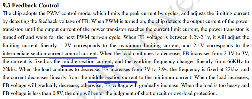
I am trying to understand how DK125 behaves in terms of output frequency, duty cycle and limiting current corresponding to the feedback voltage on the FB pin, I see the voltage on this pin is divided into ranges where the behavior is different but am not able to get the relation between the mentioned parameters (fret, duty cycle and limiting current).

I think the main reason for the confusion is that some terms are not clear to me like the following underlined in blue:

enter image description here

for "maximum limiting current" I understand it but can't get how know the value from the datasheet, other terms are not clear for me.

Link for Datasheet

So if any one can explain this part to me it will be helpful.

Thanks in advance

\$\endgroup\$

1 Answer 1

0
\$\begingroup\$

It is relatively simple if you consider that this is talking about NEGATIVE feedback, and it is regulating output VOLTAGE by feeding more current back through the opto-coupler when the output voltage starts going above the set point.
They didn't specify exactly how do you achieve the mentioned voltages, but your feedback circuit will usually have a wide range and thus be able to compensate.
You would still need to check if the mentioned voltages are achieved at the mentioned approximate loads on the output.
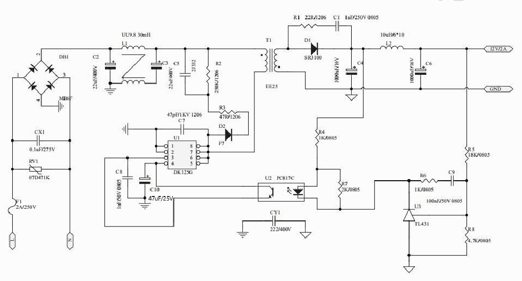
Their example circuit is a good start.
enter image description here

\$\endgroup\$

Your Answer

By clicking “Post Your Answer”, you agree to our terms of service and acknowledge you have read our privacy policy.

Not the answer you're looking for? Browse other questions tagged or ask your own question.