-2
\$\begingroup\$

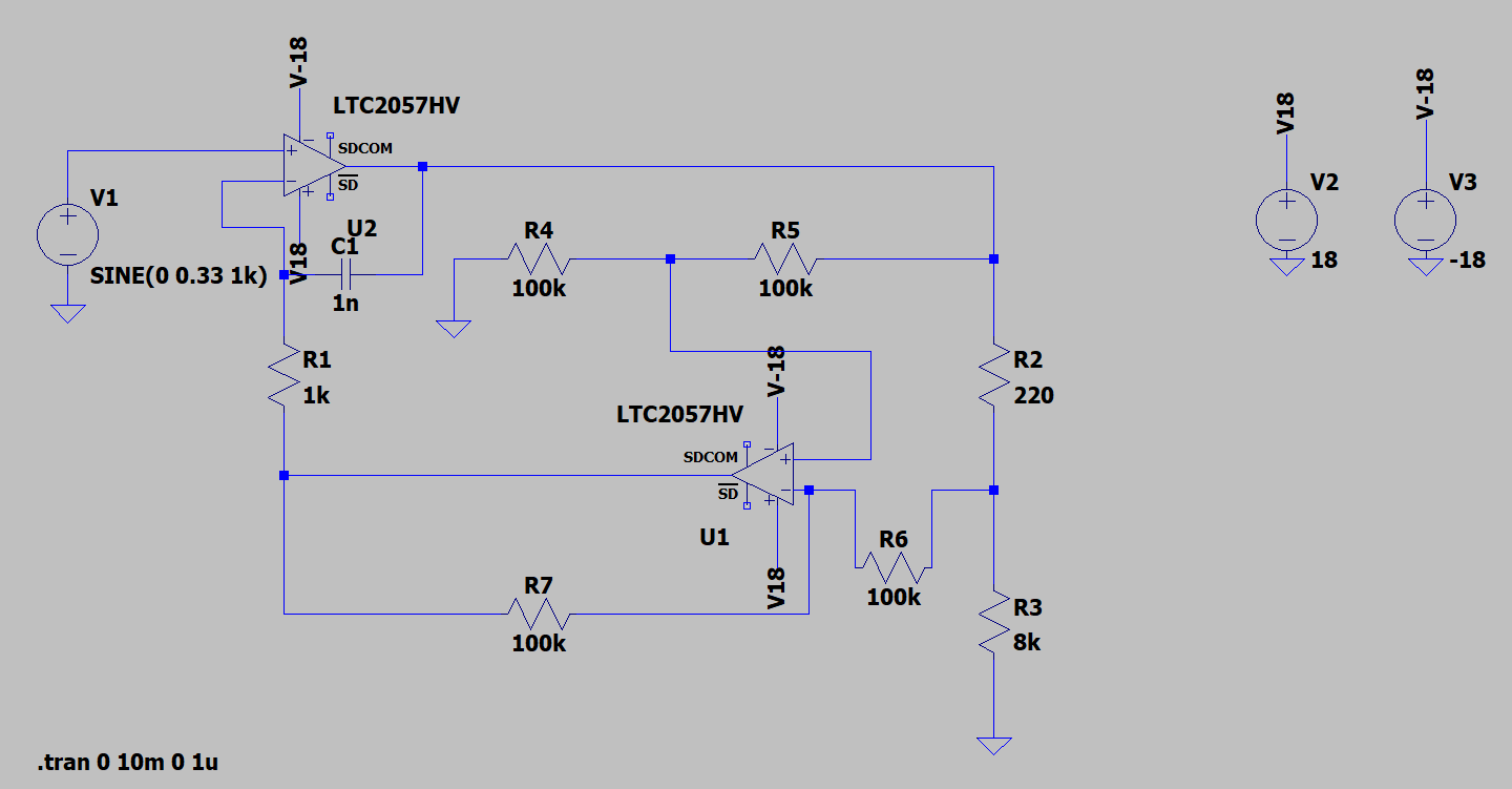
I am simulating the following voltage-controlled current source using LTspice. This design works for the application where it is going to be applied. However, the output current is not completely independent from the load, due to the non-infinitive impedance of the second op-amp. The gain is equal to 1. enter image description here
For that reason, I am trying to replace the second op-amp and the resistors R4, R5, R6 and R7 by an instrumentation amplifier configuration (AD8221), so that the input impedance will be higher and the overall performance will be enhanced. This is the schematics that I am using. The idea is that the gain has to remain 1 and the output should be the same as the previous configuration, but with less error. enter image description here
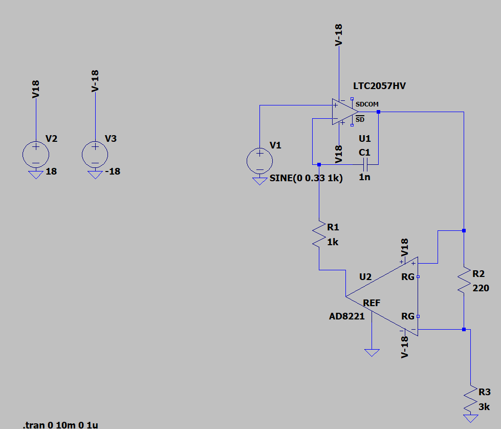
However, the simulations are not working (The message is: Singular matrix; Check node u2:56. Iteration no.18) . Could you help me solving the problem, please?

\$\endgroup\$
12
  • 1
    \$\begingroup\$ How are the simulations not working? Not the result you expected? An error message? Something else? \$\endgroup\$
    – winny
    Commented Nov 4 at 13:07
  • \$\begingroup\$ The message is: Singular matrix; Check node u2:56. Iteration no.18 \$\endgroup\$
    – neusp
    Commented Nov 4 at 14:11
  • \$\begingroup\$ You need to edit that information into your question. \$\endgroup\$
    – Null
    Commented Nov 4 at 14:13
  • \$\begingroup\$ Please, R3 is the load and IR3 is the controlled current by Vin? \$\endgroup\$ Commented Nov 4 at 14:42
  • \$\begingroup\$ Hi Francesco, Yes exactly, the load is R3. \$\endgroup\$
    – neusp
    Commented Nov 4 at 14:53

2 Answers 2

0
\$\begingroup\$

I did a quick analysis of the circuit, I hope it is correct. From it I deduced the conditions for which the current in R3 does not depend on R3:

enter image description here

\$\endgroup\$
2
  • \$\begingroup\$ Hi Francesco, thank you so much. Unfortunately, the simulations are not working for that circuit. Do you have any idea of what could be the problem? \$\endgroup\$
    – neusp
    Commented Nov 4 at 15:28
  • \$\begingroup\$ I have done a general analysis and determined the conditions for the current in the load to not depend on the load itself. Unfortunately I have not done the simulation so I do not know what to tell you about the problems in this regard. \$\endgroup\$ Commented Nov 4 at 15:33
0
\$\begingroup\$

I tried many variations of the circuit using the AD8221 and it seems to have a flaky model that works sometimes and not others with only a slight change in the circuit.

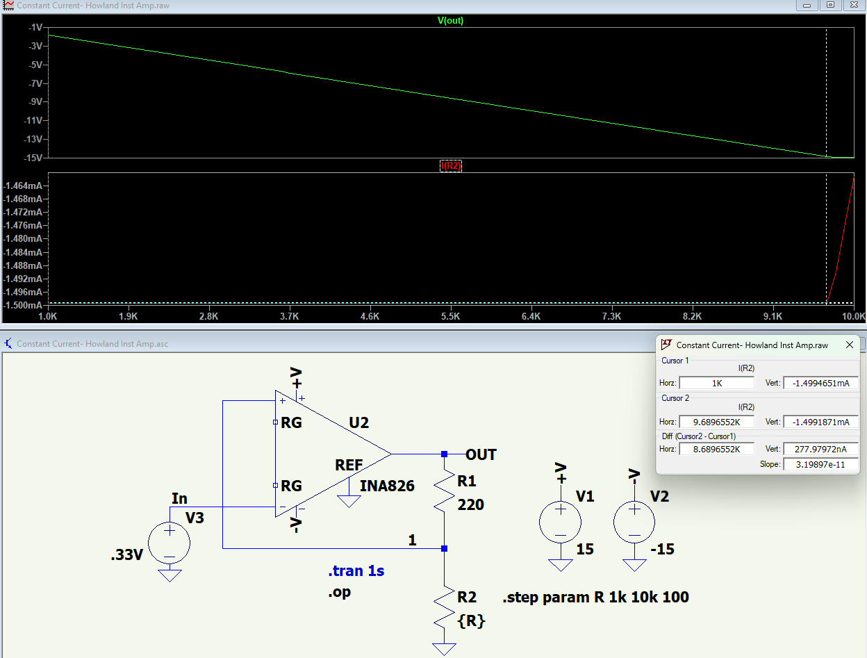
Below is an LTspice sim showing a INA826 low-cost, precision, RR output instrumentation amp configured as a simple variation of a Howland current source, which may work for you. (Note the output is out-of-phase (inverted) from the input, if that's a problem).

It shows <1µA change in current for a load change of 1kΩ to the maximum of 9.7kΩ before it saturates. (Note that for reliable operation, you should never operate the amp at its maximum voltage rating of ±18V).

enter image description here

\$\endgroup\$

Your Answer

By clicking “Post Your Answer”, you agree to our terms of service and acknowledge you have read our privacy policy.

Not the answer you're looking for? Browse other questions tagged or ask your own question.