0
\$\begingroup\$

I am currently working on a board designed around the STM32H725RGV6 and have encountered issues with it being recognised by STM32CubeProgrammer as I get the message "target not found" when connecting it to a STLINK-v3-minie. With my previous experience using H7 or F7 MCUs, they get pretty warm even while idling which mine does not.

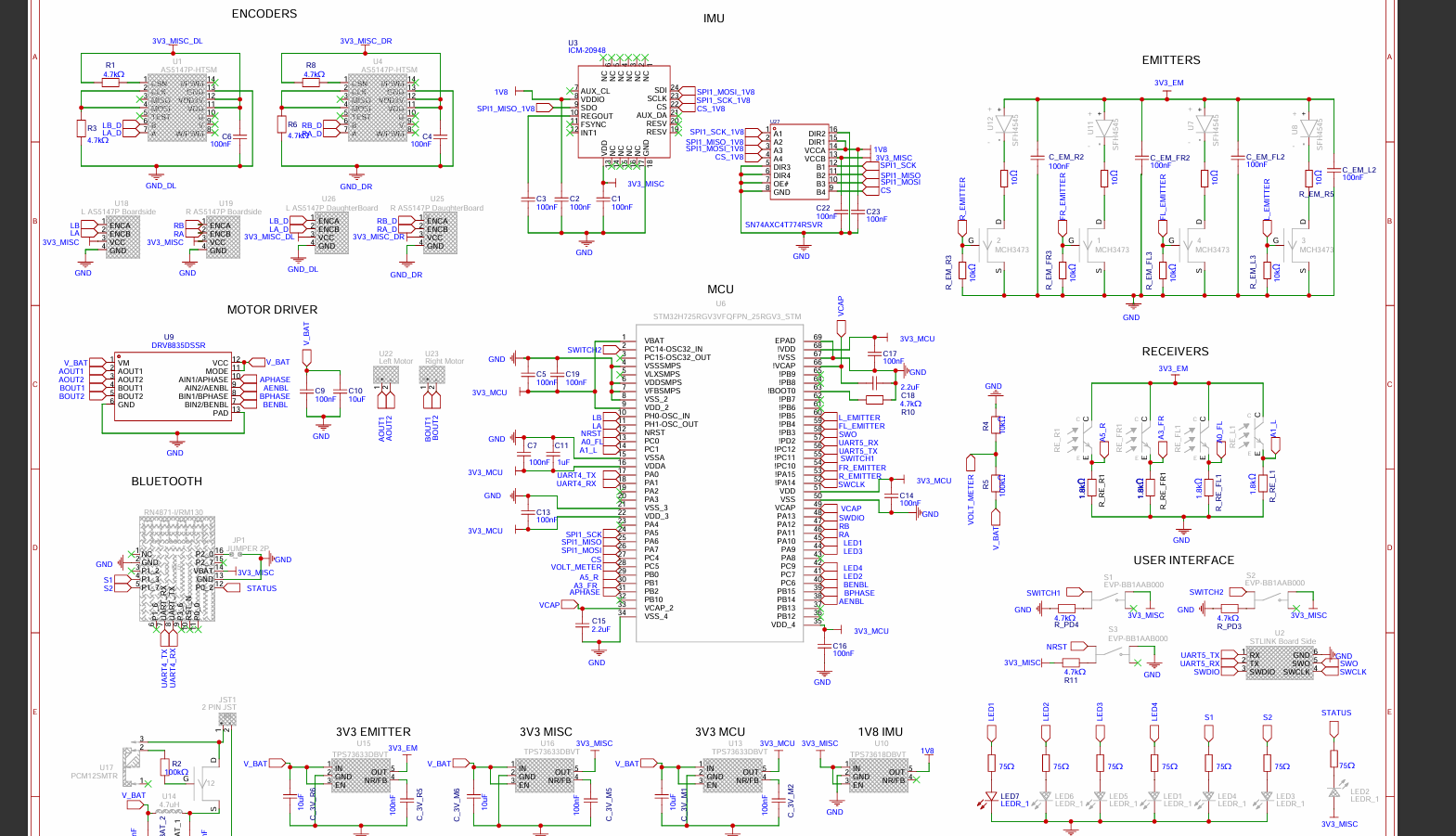
VDD is 3.3V and supplied from a LDO regulator, TPS73633. With the board fully populated except the bluetooth module, RN4871, I have verified that the MCU is receiving 3.3V through the VDD pins.

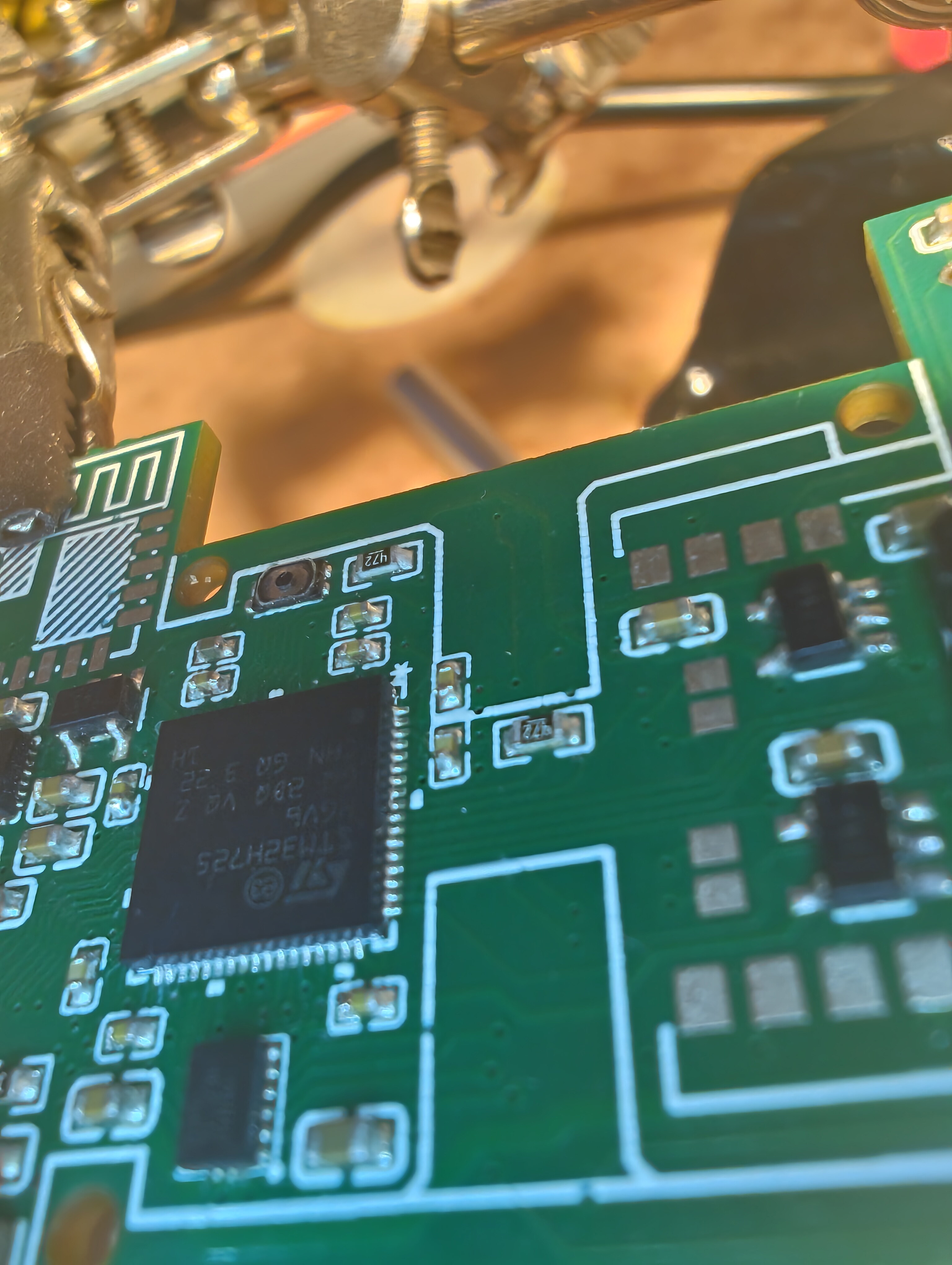
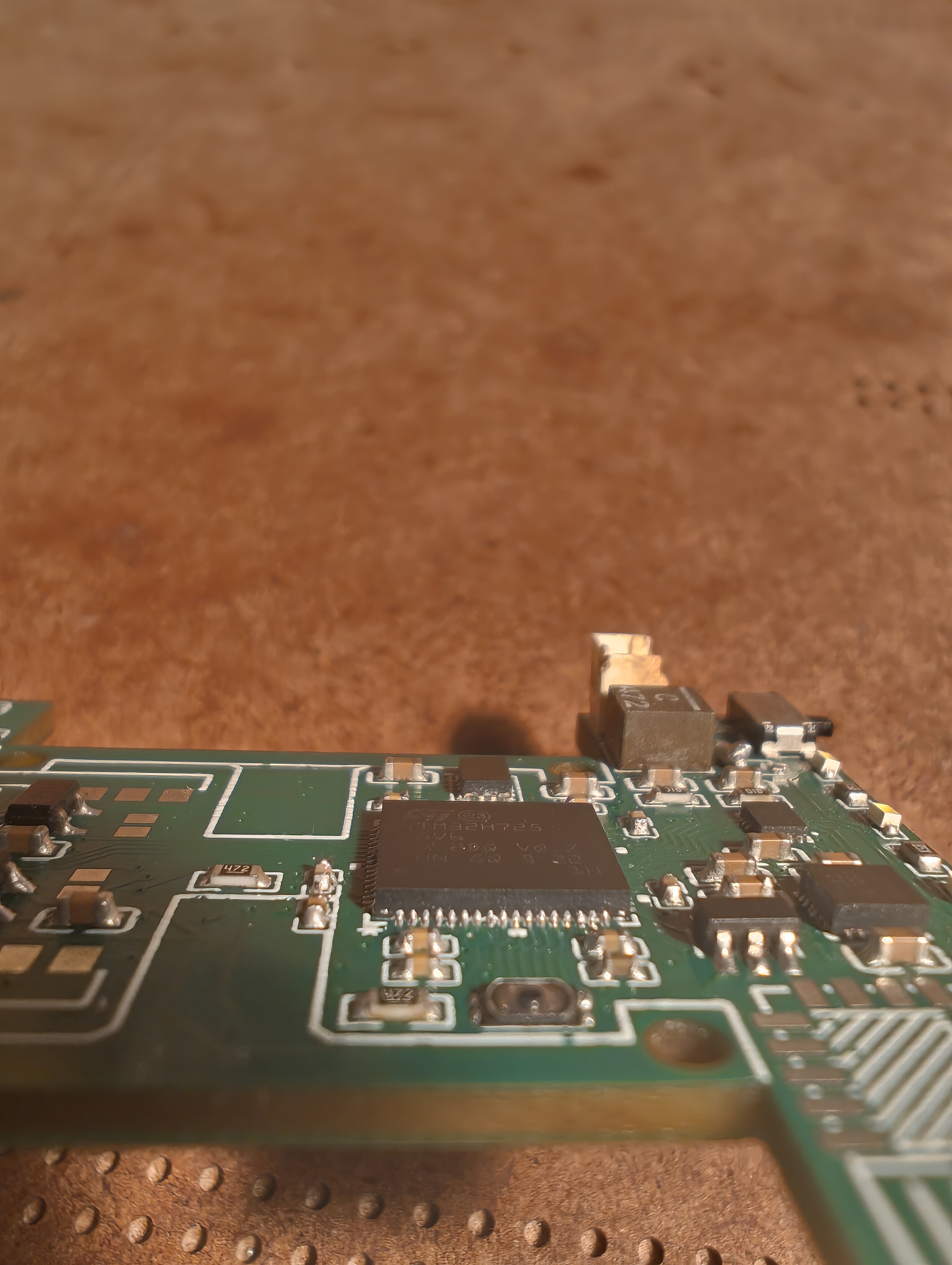
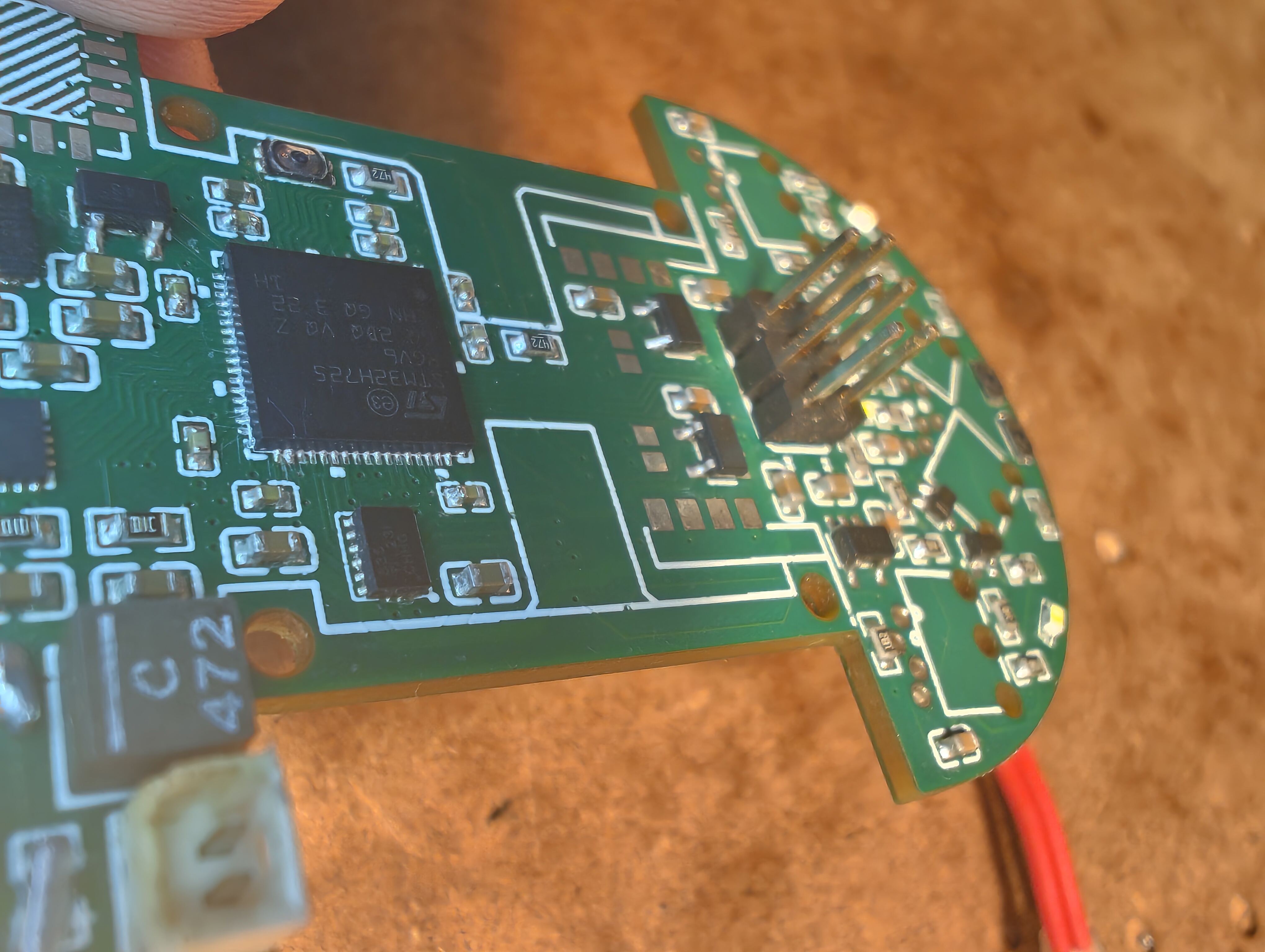
I have also checked that BOOT0 is pulled low and NRST is pulled high. 2 of the 3 VCAP pins have 2.2uF caps placed nearby and the third is connected to the other 2. I have used a multimeter and continuity tested the majority of the pins to their adjacent pins and GND to check for shorts. None were found. The board was assembled by JLC except for the MCU which I had to reflow myself. I had to reflow it 3 times until I was satisfied with how the joints looked. The board was also cleaned thoroughly with IPA.

I have read that I have to choose the correct power configuration in CubeIDE but I don't get how I would be able to do this without connecting the STLINK first.No code has been uploaded to the MCU yet anyways. I realised that I have added an extra capacitor to the VDDA pins but I don't believe this would prevent the H7 from working. Hence I have narrowed it down to the VCAP pin which had a steady output of 0.08V. I immediately believed that I had fried the MCU by reflowing it too many times so I replaced it with another one which only took 2 tries to reflow. After checking for shorts, the voltage at the VCAP pins now seems to oscillating from 0V to 0.12V slowly. I don't have access to a oscilloscope currently but my multimeter still picks up on this oscillation. I only have one more MCU on hand so I don't want to try with my last one.

Any advice is very welcome. I have attached my schematic, PCB layout and photos of the MCU's solder joints. The board is very space constrained. Schematic
enter image description here

enter image description here

enter image description here enter image description here

enter image description here

\$\endgroup\$
17
  • \$\begingroup\$ Do you try with another know good 3.3V supply? — (Is it for a gamepad? :) \$\endgroup\$
    – user317139
    Commented Nov 9 at 21:53
  • \$\begingroup\$ First things first. Have you checked that the STM32 is at correct orientation, not rotated by 90 or 180 degrees? Which is pin 1 mark on your board, the star-alike white dot? You are not supposed to pull NRST high, it's pulled to the MISC supply so it must be present then, an there is no capacitor on NRST. \$\endgroup\$
    – Justme
    Commented Nov 10 at 8:35
  • \$\begingroup\$ @Burglups I have used these LDOs before and they have worked without any problems. Also to answer your question about it being a gamepad, it's actually a micromouse. \$\endgroup\$
    – DanielR
    Commented Nov 10 at 9:53
  • \$\begingroup\$ @Justme pin 1 is denoted by the asterisk and the mcu is oriented correctly. Could you elaborate more on what you mean regarding the NRST pin? \$\endgroup\$
    – DanielR
    Commented Nov 10 at 9:59
  • \$\begingroup\$ Guess I should've read everything about every pin. The NRST function shouldn't be critical to my project so I'll try removing the switch and resistor and replacing it with a single capacitor to ground. \$\endgroup\$
    – DanielR
    Commented Nov 10 at 10:13

1 Answer 1

0
\$\begingroup\$

@Justme @Burglups Thank you for your responses. In the datasheet it states that the specific variant of STM32H725 only features an SMPS and no internal LDO, which my schematic does not fall in line with. I connected the MCU to be powered in LDO supply when I should've configured it to run in SMPS supply. The datasheet is not very clear; for future reference there is some more information in this forum post: VCAP voltage issue

\$\endgroup\$
1
  • \$\begingroup\$ Thank you for the feedback. Yes, datasheets—especially for STM32—can sometimes be unclear. It often feels like these MCUs need to be understood based on how they are fabricated rather than how they are documented. \$\endgroup\$
    – user317139
    Commented Nov 16 at 14:17

Your Answer

By clicking “Post Your Answer”, you agree to our terms of service and acknowledge you have read our privacy policy.

Not the answer you're looking for? Browse other questions tagged or ask your own question.